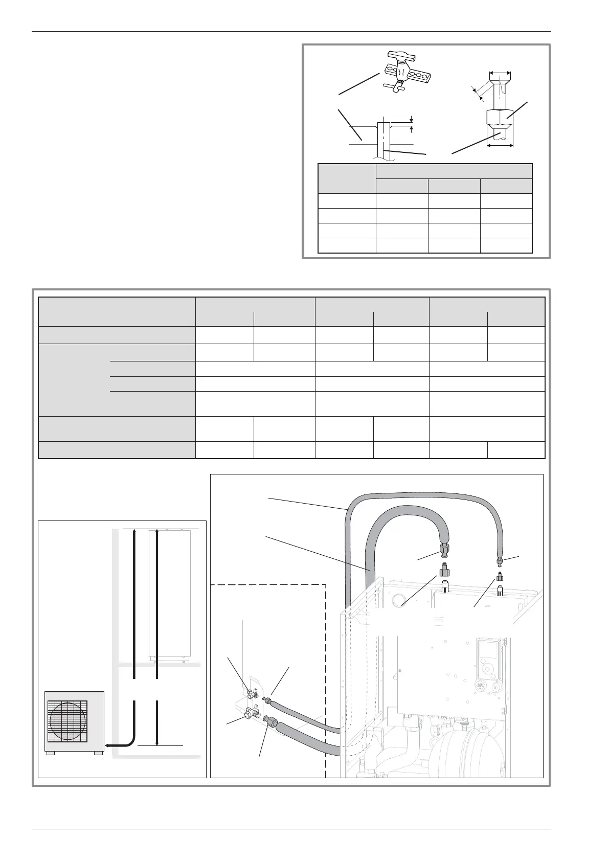
gure 19 - Refrigeration connections (authorised diameters and lengths)
HP model
Alféa Extensa Duo A.I. 5, 6 Alféa Extensa Duo A.I. 8 Alféa Extensa Duo A.I. 10
gas liquid gas liquid gas liquid
Outside unit connections 1/2" 1/4" 5/8" 1/4" 5/8" 3/8"
Refrigeration
connections
Diameter: (D1) 1/2" (D2) 1/4" (D1) 5/8" (D2) 1/4" (D1) 5/8" (D2) 3/8"
Minimum length (L) 5 5 5
Maximum length** (L) 30 30 30
Maximum Height
Difference** (D)
20 20 20
Male-female adapter
(reduction)
(R1)
1/2" - 5/8"
(R2)
1/4" - 3/8"
without
(R2)
1/4" - 3/8"
without
Hydraulic unit connections 5/8" 3/8" 5/8" 3/8" 5/8" 3/8"
**: Including any additional lling (see "Additional lling", page 27).
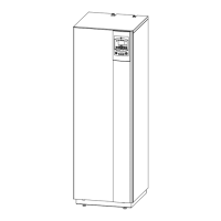
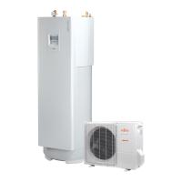
Heat pump
Hydraulic unit
Heat Pump
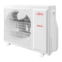
Outdoor unit
"Gas" refrigeration
connection
diameter D1
"Liquid" refrigeration
connection
diameter D2
Flared
nut
Flared nut
R2 adapter
(depending on
model)
R1 adapter
(depending on
model)
Flared
nut
Flared
nut
"Liquid”
valve
“Gas”
valve
Hydraulic unit
Outdoor unit
gure 18 - Flaring of the ared connections
Flaring tool
Pipe
Nut
are
B
L
C
Pipe ø
Dimensions in mm
L B
0
/
-0.4
C
6.35 (1/4") 1.8 to 2 9.1 17
9.52 (3/8") 2.5 to 2.7 13.2 22
12.7 (1/2") 2.6 to 2.9 16.6 26
15.88 (5/8") 2.9 to 3.1 19.7 29
3.2.2 Creating the arings
- Cut the pipe to an appropriate length with a pipe-cutter
without damaging it.
- Carefully deburr it, holding the pipe pointing downward
to avoid introducing lings into the pipe.
- Remove the ared connection nut situated on the
valve to be connected and slide the pipe into the nut.
- Proceed to are it, letting the pipe protrude out of the
aring tool's tube.
- After aring, check the state of the working radius (L).
This must not present any scratches or signs of
fracturing. Also check the dimension (B).
Installation and Operating Manual "1821- EN"
Alféa Extensa Duo A.I. Heat Pump
- 22 -