" Before any maintenance operation, ensure that the general power supply is switched o.
" Electrical installation must be performed in accordance with current regulations.
5 Electrical connections
The electrical diagram for the hydraulic unit is shown on gure 48, page 73.
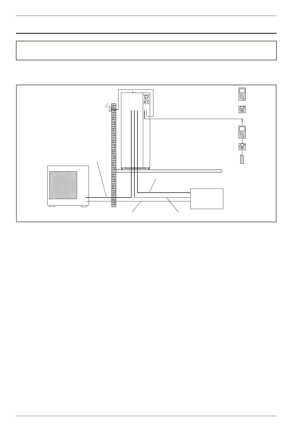
gure 33 - Overall layout of electrical connections for a simple installation (1 heating circuit)
Outside sensor
Cable 2 x 0.75 mm²
Connection outdoor unit and hydraulic unit
(phase, neutral, earth, communications bus)
Cable 4 x 1.5 mm²
Room sensor A78 (battery/option)
Room sensor A59 (battery/option)
Room sensor A75 (option)
Cable 2 x 0.5 mm²
Room sensor A59 (option)
Cable 2 x 0.5 mm²
Typass ATL (option)
Cable 3 x 0.5 mm²
Electrical backup power supply
(see table below)
DHW power supply
(phase, neutral, earth) Cable 3 x 1.5 mm²
General electrical supply (phase, neutral, earth)
(see table below)
Electrical
Board
or
or
or
or
Installation and Operating Manual "1821- EN"
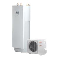
Alféa Extensa Duo A.I. Heat Pump
- 36 -