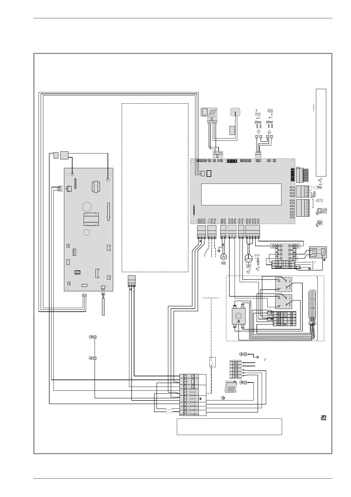
gure 48 - Electrical wiring of hydraulic unit (excluding connections made by installer)
X10
X11X12
X13
X14
X15
X30
X50
X70
X75
X80
X82
X83
X84
X86
X100
C.C
X60
Défauts externes/
External defaults
Délestage /Power shedding
Tarifs (HP/HC; Jour/Nuit)
Tariffs peak times/ off-peak times
Options
0/I
M
2a
1a
1b
2b
EX1
EX2
EX3
L
N
3
2
1
Départ /
Flow sensor
Retour /
Return sensor
L
N
COM
RP ECS
L
N
L
N
230V
Contact d'organe externe
External device connection
ACI
Electrode
Ballon ECS /
DHW Tank
+
-
1
2
3
4
5
L
N
COM
L
L
N
OPTION 2 CIRCUITS
2 circuits option
BK
BN
BU
Sonde Condensation/
Condensation Sensor
CN21
A1 A2
B1 B2
L
N
( ) 3KW
(=) 6KW
L
1
2
3
4
5
A1
A2
14
11
A1
A2
14
11
Ou/
Or
Ou/
Or
1+N
230 V
RD
BU
GN/YE
BN
L1
N
1 2
3
L
N
T3.15AH250V, 5x20 mm, IEC 60127-1
T6.3AH250V, 5x20 mm, IEC 60127-1
/
Fuse specifications
Caractéristiques fusibles
FUSE 250V/3.15A
FUSE 250V/6.3A
Connection to terminal blocks and power relay
(see gure 37, page 40)
Connections on the heat pump
controller, accessories and options
(see gure 38, page 41)
Electrode
Options
Fuse specications
DHW
tank
Flow
sensor
Condensation
sensor
2 circuit option
Monophase electrical backup
Power limitation
Taris (day/night)
External faults
External
component contact
Return
sensor
Installation and Operating Manual "1821- EN" - 73 -
Alféa Extensa Duo A.I. Heat Pump