5.3 Electrical connections
on the hydraulic unit side
Access to connection terminals:
- Remove the front plate.
- Open the power control box.
- Make the connections according to the diagram (gure 37).
Do not place the sensor and power supply lines parallel
to each other to avoid interference due to voltage spikes
in the power supply.
Make sure that all electrical cables are housed in the
areas provided for this purpose.
• Interconnection between outdoor unit and
hydraulic unit
Match up the terminal block markers on the hydraulic
unit to those of the outdoor unit exactly when connecting
the interconnection cables.
An incorrect connection could result in the destruction
of one or other of the units.
• Electrical backup
If the heat pump is not installed with a boiler connection:
- Connect the power supply for the backup to the
electrical panel.
• Boiler connection (option)
" If the boiler connection option is used, the
electric backup option must not be connected.
- Please refer to the instructions supplied with the boiler
connection kit.
- Please refer to the instructions supplied with the boiler.
• Second heating circuit (option)
- Refer to the instructions supplied with the double
hydraulic circuit kit.
• Contract with Energy Supplier
The heat pump can be set to operate within particular
types of energy contract, e.g. o-peak, day/night.
In particular, domestic hot water (DHW) at the comfort
temperature will be produced at o-peak times when
electricity is at its cheapest.
- Connect the "energy supplier" to the EX2 input.
- Set the DHW conguration to "O-Peak".
• 230V on input EX2 = "Peak Hours” information
activated.
• Power limitation or EDR (Energy Demand
Reduction)
Power limitation is designed to reduce electricity
consumption when it is too high for the contract signed
with the energy supplier.
- Connect the power limiter device to input EX1. Heat
pump and DHW backups will be shut o in the event
of over-consumption by the dwelling.
• 230 V on input EX1 = power limitation in progress
• Faults external to the heat pump
Any component which reports back information
(Underoor heating safety switch, thermostat, pressure
switch, etc.) may signal an external problem and stop
the heat pump.
- Connect the external component to input EX3.
• 230 V on input EX3 = heat pump stopped
(system displays Error 369).
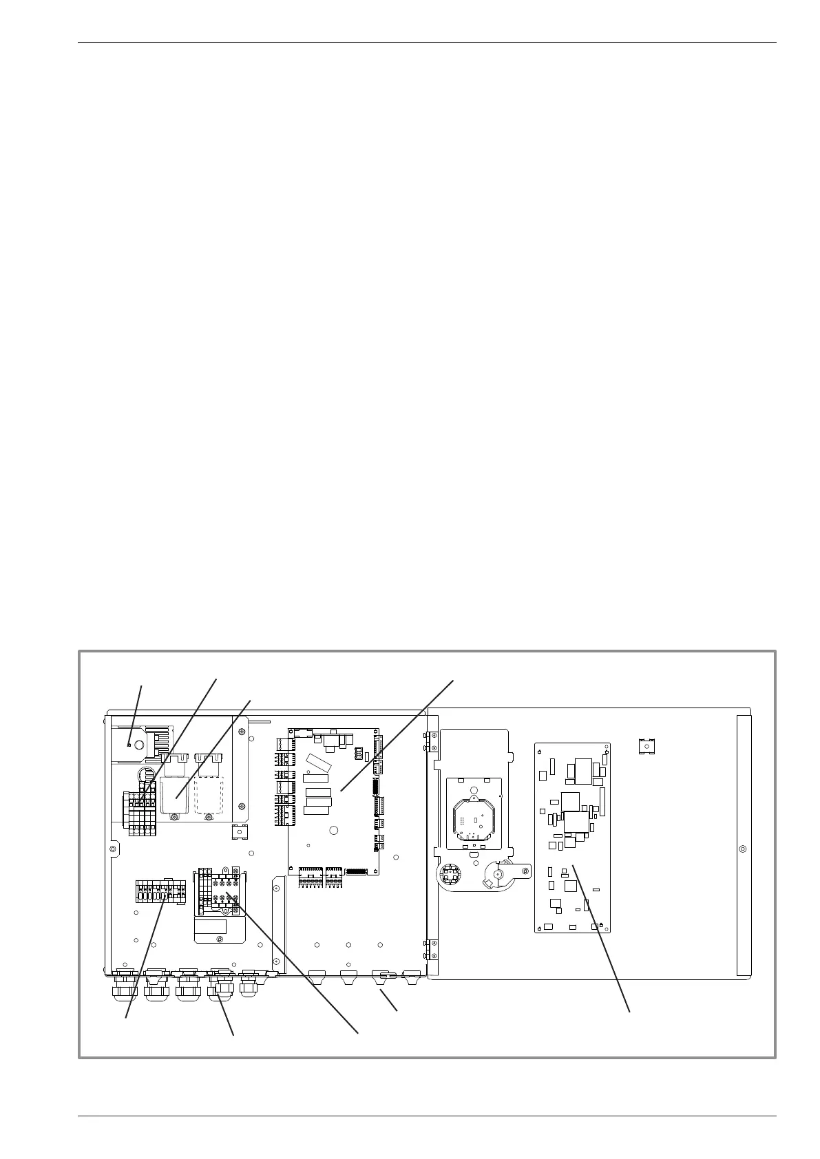
gure 36 - Description of the hydraulic module's electrical control box
HP controller
Cable grommets (power)
Interface Board
Cable grommets (sensors)
DHW Relay + Terminal
Terminal
Power supply terminal block
Power Relay for electric backup
Safety thermostat
Installation and Operating Manual "1821- EN" - 39 -
Alféa Extensa Duo A.I. Heat Pump