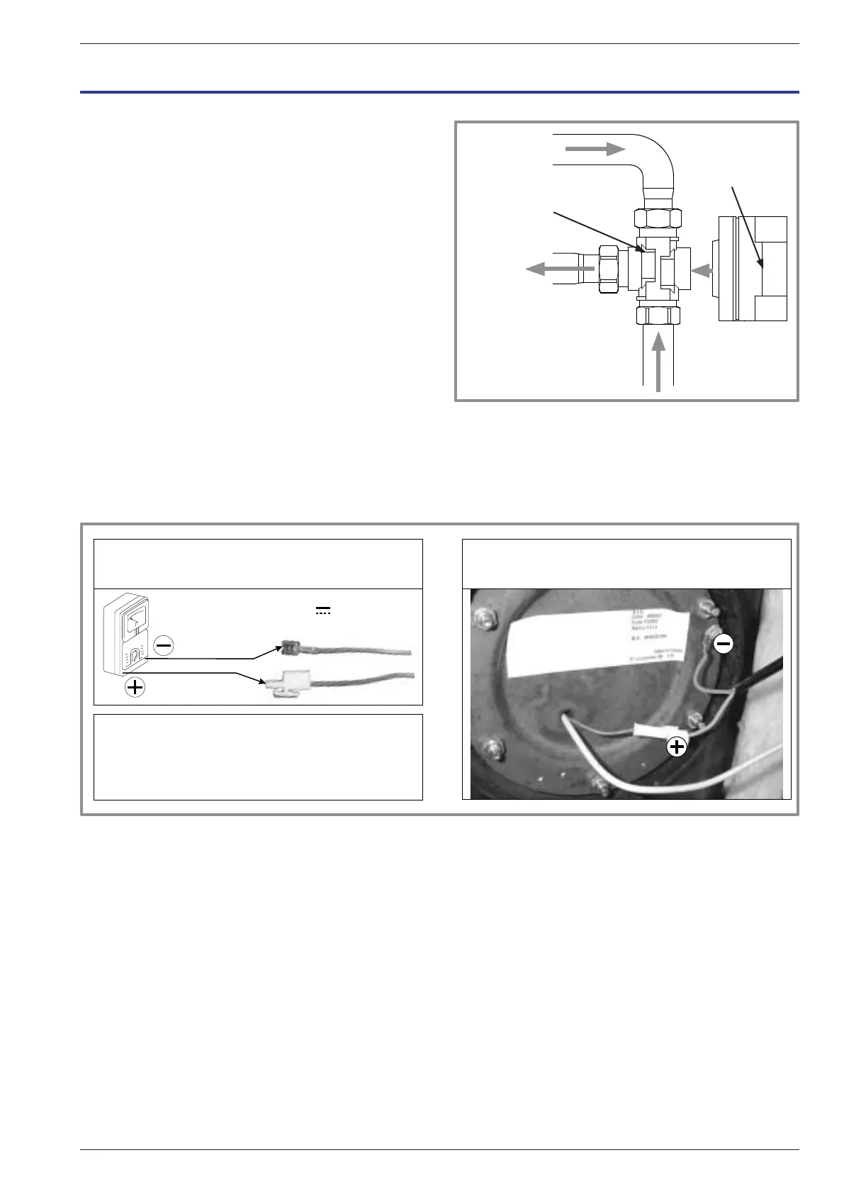
gure 50 - Mounting the distribution valve
Return from
the heating circuit
B
A
AB
Return from DHW tank
Valve
Valve motor
Flow towards
exchanger
13.1 Emptying the hydraulic unit
- Remove the front panel of the hydraulic unit.
- Place the distribution valve in the middle position.
- Open the drain valve (ref. 5x).
- Check that the hydraulic unit's bleeder valve opens
automatically (ref. 6).
- Open the installation’s bleeder valve(s).
13.2 Distribution valve
Ensure the distribution valve is tted in the correct
direction:
Channel AB: outlet towards the hydraulic unit.
Channel A open: Return from DHW tank.
Channel B open: Return from the heating circuit.
13.3 ACI check
- Check polarity.
- Check voltage: With the appliance powered on,
the voltage value must be positive and lie between
+10 and +13 V DC.
gure 51 - ACI check
13 Other maintenance
U = + 0 + 6,5 V
Contrôle de l'alimentation ACI Raccordement
Raccordement ACI :
Le sur la masse du ballon,
Le sur le connecteur de l'électrode.
-
+
à
10 13
ACI power supply control Connection
ACI connection:
- to the tank body,
+ to the electrode connector.
to
Installation and Operating Manual "1821- EN" - 77 -
Alféa Extensa Duo A.I. Heat Pump