5.4 Outside sensor
The outside sensor is required for correct operation of
the heat pump.
Please see the tting instructions on the sensor’s
packaging.
Place the sensor on the coldest side of the building,
generally the northern or north-western side.
It must not be exposed to morning sun.
It must be installed so as to be easily accessible but at
least 2.5m from the ground.
It is essential that it is not placed near any sources of
heat such as ues, upper parts of doors and windows,
near extractor vents, under balconies and eaves,
or anywhere which would insulate the sensor from
variations in the outdoor air temperature.
- Connect the outside sensor to connector X84
(terminals M and B9) on the heat pump control board.
5.5 Room sensor (option)
The room sensor is optional.
Please see the tting instructions on the sensor’s
packaging.
The sensor must be installed in the living room area on
an unobstructed wall. It must be installed so as to be
easily accessible.
Avoid direct sources of heat (chimney, television,
cooking surfaces, sun) and draughty areas (ventilation,
door, etc.).
Draughts in buildings are often brought about by cold air
blowing through the electrical ducting. Lag the electrical
ducts if there is a cold draught behind the room sensor.
5.5.1 Installing a room sensor
• Room sensor A59
- Connect the sensor's power supply to connector X86
on the HP control board using the connector provided
(terminals 2 and 3).
• Room sensor A75
- Connect the sensor's power supply to connector X86
on the HP control board using the connector provided
(terminals 2 and 3).
5.5.2 Installing a Typass ATL
- Connect the Typass ATL to connector X86
on the HP control board using the connector provided
(terminals 1, 2 and 3).
5.5.3 Fan convector zone
If the installation is equipped with fan convectors or
dynamic radiators, do not use a room sensor.
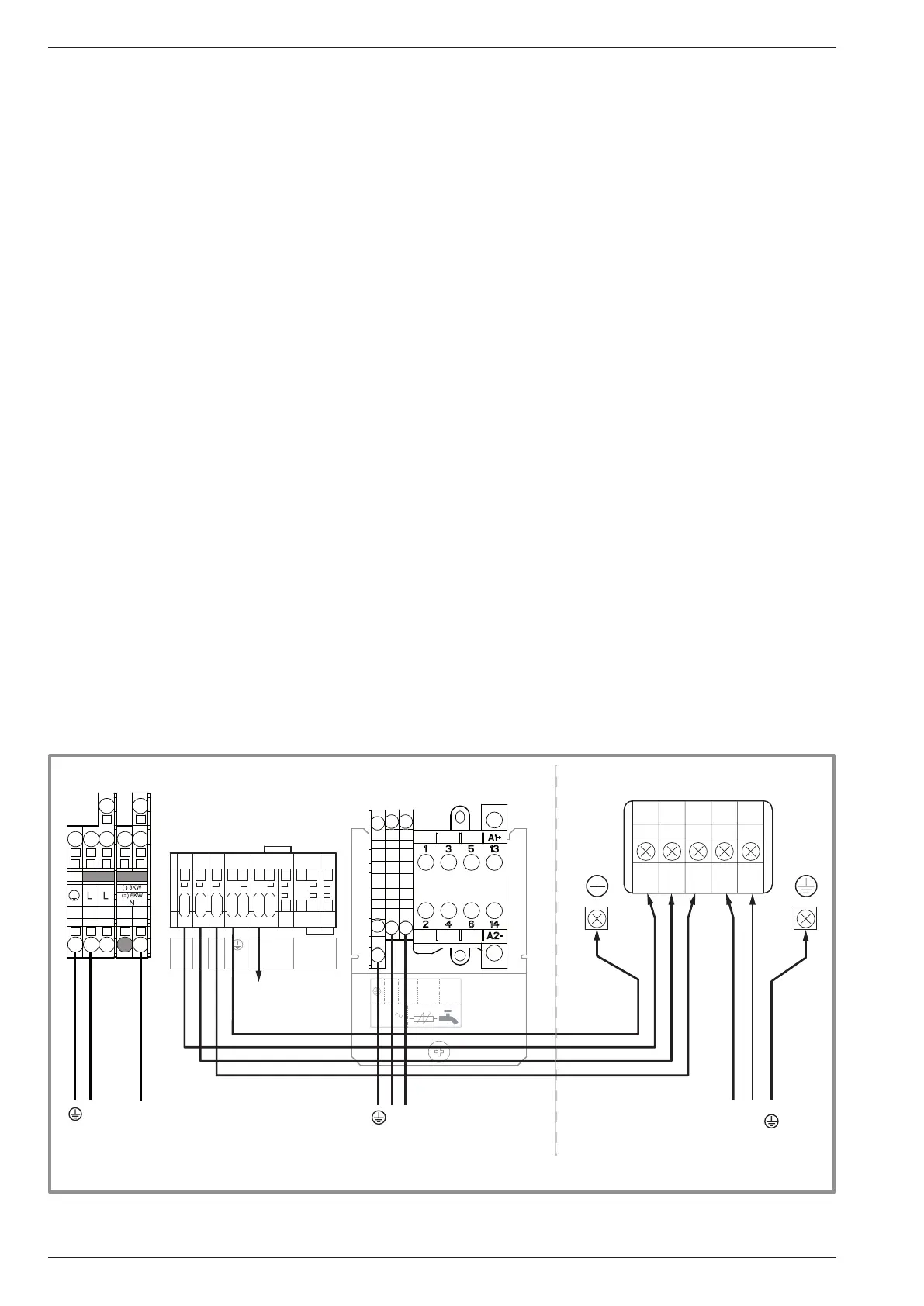
gure 37 - Connection to terminal blocks and power relay
230 V
L
N
L N
2
4
L
N
1 2 3
4 5 6 7
1
2
3
4
5
L
N
COM
L
1 2 3 L N
L
N
L
N
Outdoor unitHydraulic unit
Power supply
230 V
Power supply
Domestic Hot Water
230 V
towards external
component
contact*
red
blue
brown
green/yellow
Interconnection
between outdoor unit
and hydraulic unit
Power supply
Electrical backup
230 V
Installation and Operating Manual "1821- EN"
Alféa Extensa Duo A.I. Heat Pump
- 40 -