Ref. Name
Da Automatic condensate outlet
Dm Manual condensate drain valve
Dm1 Manual condensate drain valve
ER Elektronikon II regulator
S3 Emergency stop button
2.2 Air flow
Flow diagrams
Workplace compressors
References
Ref. Description
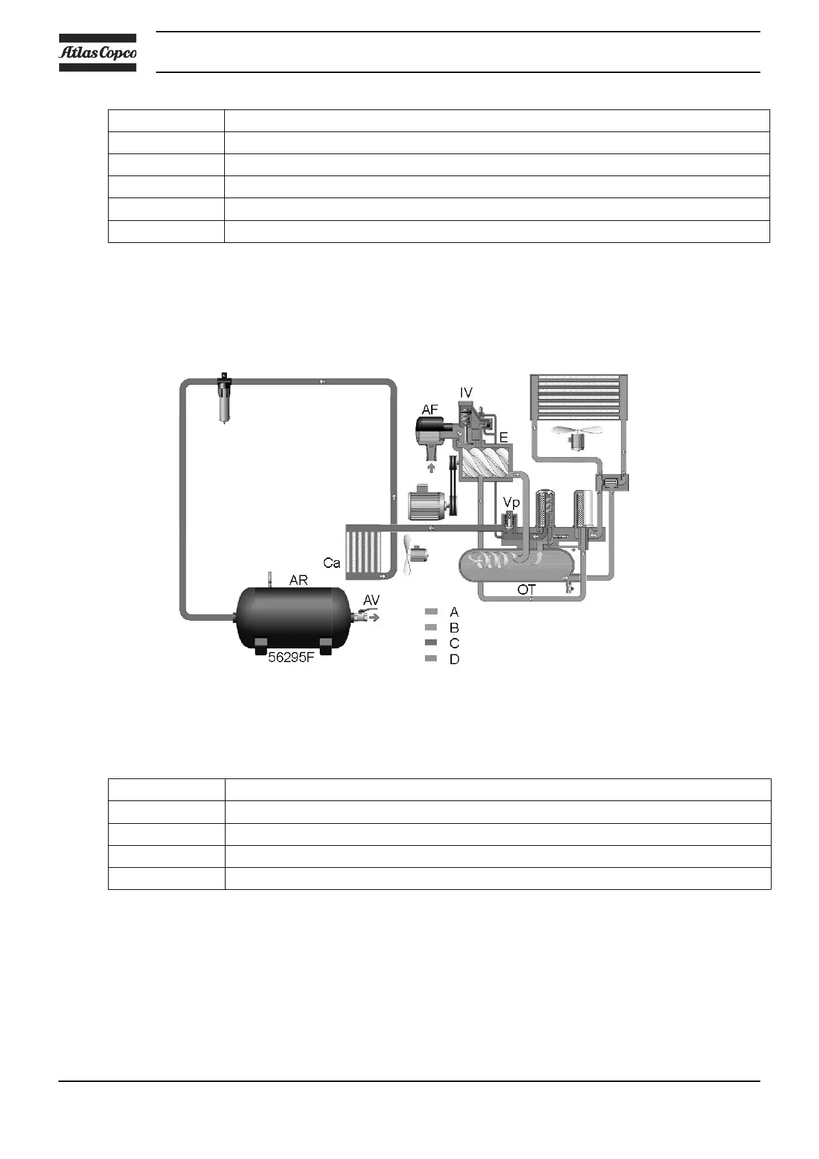
A Air inlet
B Compressed air/oil
C Compressed air
D Oil
Description
Air drawn in through filter (AF) and open inlet valve (IV) into compressor element (E) is
compressed. Compressed air and oil flow into the air receiver/oil separator vessel (OT). Next, the
compressed air flows through minimum pressure valve (Vp) and the air cooler.
Air is discharged through outlet valve (AV).
Instruction book
12 API161475

 Loading...