166
7679H–CAN–08/08
AT90CAN32/64/128
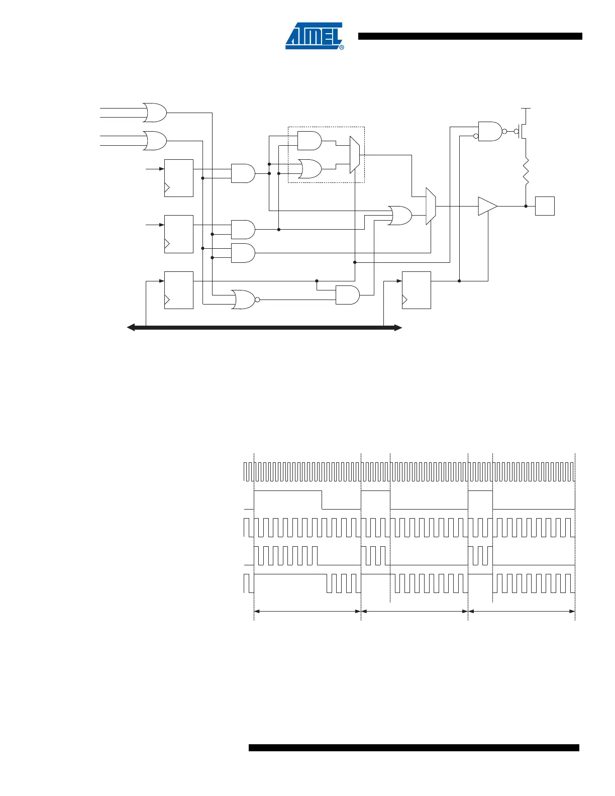
Figure 15-2. Output Compare Modulator, Schematic
15.2.1 Timing Example
Figure 15-3 illustrates the modulator in action. In this example the Timer/Counter1 is set to oper-
ate in fast PWM mode (non-inverted) and Timer/Counter0 uses CTC waveform mode with toggle
Compare Output mode (COMnx1:0 = 1).
Figure 15-3. Output Compare Modulator, Timing Diagram
In this example, Timer/Counter0 provides the carrier, while the modulating signal is generated
by the Output Compare unit C of the Timer/Counter1.
PORTB7 DDRB7
DQDQ
Pin
DATABUS
COM0A1
COM0A0
OC0A / OC1C / PB7
COM1C1
COM1C0
Modulator
1
0
OC1C
DQ
OC0A
DQ
(From T/C1
Waveform Generator)
(From T/C0
Waveform Generator)
0
1
Vcc
1 2
OC0A
(CTC Mode)
OC1C
(FPWM Mode)
PB7
(PORTB7 = 0)
PB7
(PORTB7 = 1)
(Period)
3
clk
I/O

 Loading...


