344
7679H–CAN–08/08
AT90CAN32/64/128
1. 1. Set XA1, XA0 to “10”. This enables command loading.
2. Set DATA to “0000 0000”. This is the command for No Operation.
3. Give XTAL1 a positive pulse. This loads the command, and the internal write signals
are reset.
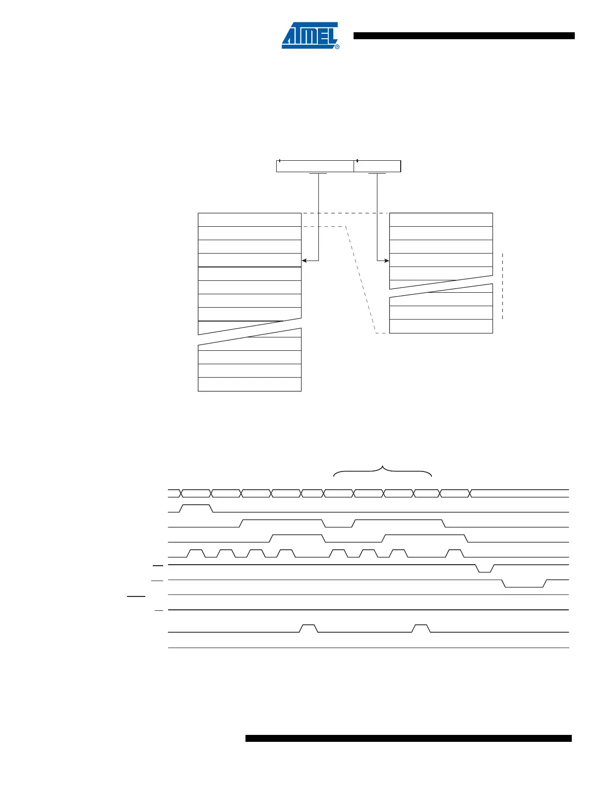
Figure 25-2. Addressing the Flash Which is Organized in Pages
(1)
Note: 1. PCPAGE and PCWORD are listed in Table 25-11 on page 341.
Figure 25-3. Programming the Flash Waveforms
(1)
Note: 1. “XX” is don’t care. The letters refer to the programming description above.
PROGRAM MEMORY
WORD ADDRESS
WITHIN A PAGE
PAGE ADDRESS
WITHIN THE FLASH
INSTRUCTION WORD
PAGE
PCWORD[PAGEMSB:0]:
00
01
02
PAGEEND
PAGE
PCWORDPCPAGE
PCMSB PAGEMSB
PROGRAM COUNTER
0x10 ADDR. LOW
ADDR. HIGH
DATA LOW DATA HIGH ADDR. LOW DATA LOW DATA HIGH
RDY/BSY
WR
OE
RESET +12V
PAGEL
BS2
DATA
XA1
XA0
BS1
XTAL1
XX XX
XX
ABCDEBCDEGH
F

 Loading...


