52
7679H–CAN–08/08
AT90CAN32/64/128
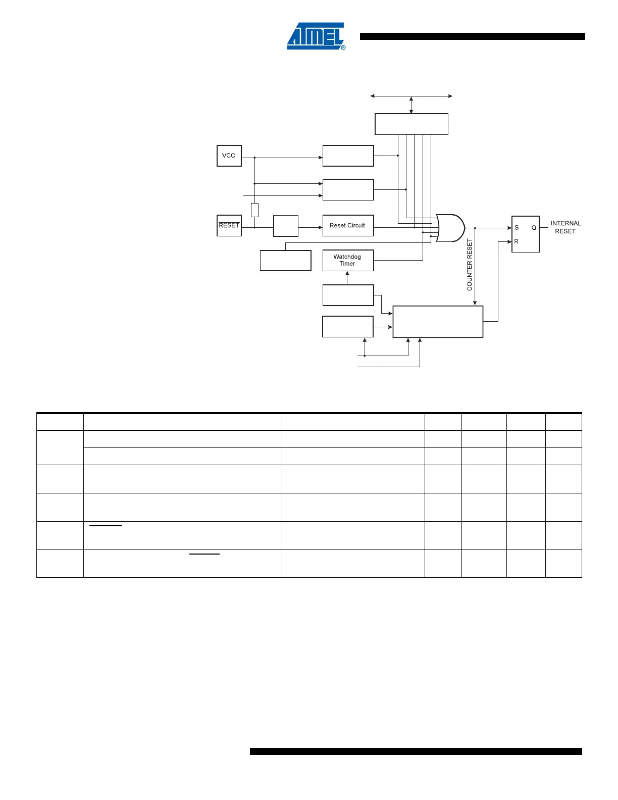
Figure 7-1. Reset Logic
Note: 1. The Power-on Reset will not work unless the supply voltage has been below V
POT
(falling)
7.1.3 Power-on Reset
A Power-on Reset (POR) pulse is generated by an On-chip detection circuit. The detection level
is defined in Table 7-1. The POR is activated whenever V
CC
is below the detection level. The
POR circuit can be used to trigger the start-up Reset, as well as to detect a failure in supply
voltage.
A Power-on Reset (POR) circuit ensures that the device is properly reset from Power-on if V
CC
started from V
POR
with a rise rate upper than V
CCRR
. Reaching the Power-on Reset threshold
voltage invokes the delay counter, which determines how long the device is kept in RESET after
MCU Status
Register (MCUSR)
Brown-out
Reset Circuit
BODLEVEL [2..0]
Delay Counters
CKSEL[3:0]
CK
TIMEOUT
WDRF
BORF
EXTRF
PORF
DATA BUS
Clock
Generator
Spike
Filter
Pull-up Resistor
JTRF
JTAG Reset
Register
Watchdog
Oscillator
SUT[1:0]
Power-on Reset
Circuit
Table 7-1. Reset Characteristics
Symbol Parameter Condition Min. Typ. Max. Units
V
POT
Power-on Reset Threshold Voltage (rising) 1.4 2.3 V
Power-on Reset Threshold Voltage (falling)
(1)
1.3 2.3 V
V
POR
Vcc Start Voltage to ensure
internal Power-on Reset signal
- 0.05 GND + 0.05 V
V
CCRR
Vcc Rise Rate to ensure
internal Power-on Reset signal
0.3 V/ms
V
RST
RESET Pin Threshold Voltage
0.2
Vcc
0.85
Vcc
V
t
RST
Minimum pulse width on RESET Pin Vcc = 5 V, temperature = 25 °C 400 ns

 Loading...


