Copyright © 2006-2009 AudioNote Kits
www.AudioNoteKits.com
audionotekits@rogers.com
Page 25
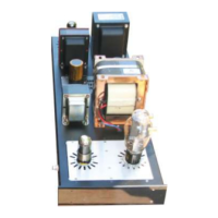
Install the two 10R resistors into
position.
The trick here is to route the 10 ohm
red resistor through to the 250 ohm
resistor as shown.
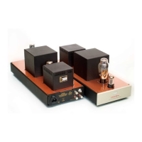
Curl the leads around for good
mechanical connection then solder
into position and cut the remaining leg
off. ALWAYS hold the excess piece so
that it does not go flying off into space
as this can be dangerous.
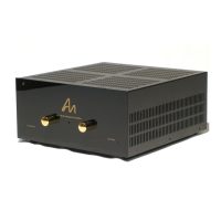
You will see that we have a GROUND
that goes down the middle of the
board. Take the 20 guage Black PTFE
wire supplied and strip at least 1 inch
of insulation.
Then thread this through the two
resistors as shown in these pictures.
Do not solder yet...
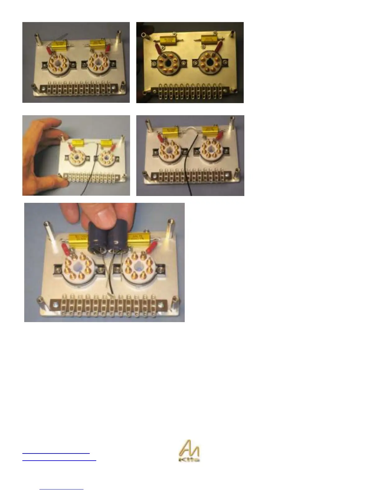
Now before you solder we will want to add each 220uf 100v
Electrolytic capacitor – this is a little tricky so take your
time.
Basically if you look at the schematic you will see the 2x
220uF capacitors situated on the cathode.
Please read through this section before starting to install
the capacitors.
We are going to position the two capacitors something like
the picture opposite.
Remember, these are electrolytic capacitors so they must
be connected with correct polarity in mind.