Copyright © 2006-2009 AudioNote Kits
www.AudioNoteKits.com
audionotekits@rogers.com
Page 27
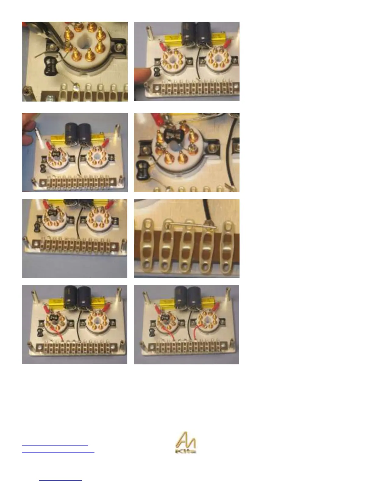
Now you can install the 47pf capacitor
into position – refer to the graphic.
On the graphic we have 12 positions
on the tag strip – make sure to align
the correct position with your
connections (in this case the 47pf cap
connects to position 11).
Wrap the leg around the valve base
post and solder and then cut off
excess lead.
Now install the second 47pf capacitor
as shown opposite (also refer to the
wiring diagram).
Now add the ground LEAD.
You will notice on the graphic that we
have 3 grounds in the middle of the
tag strip – positions 6 7 & 8 – let’s add
a piece of wire to connect all three as
shown here.
NOTE: These pictures are incorrect.
Recently we have replaced these
wires with 10K resistors that have
been relocated from the driver board*
So, connect a 10K resistor between
-OUT (position 9 on tag strip) and pin
5 on the left-hand valve base.
Connect the other between +OUT
(position 5) and pin 5 on the right-hand
valve base.
* Please note that other pictures in this section are incorrect also as they omit the 2x 10K resistors introduced in this last
step.