Copyright © 2006-2009 AudioNote Kits
www.AudioNoteKits.com
audionotekits@rogers.com
Page 28
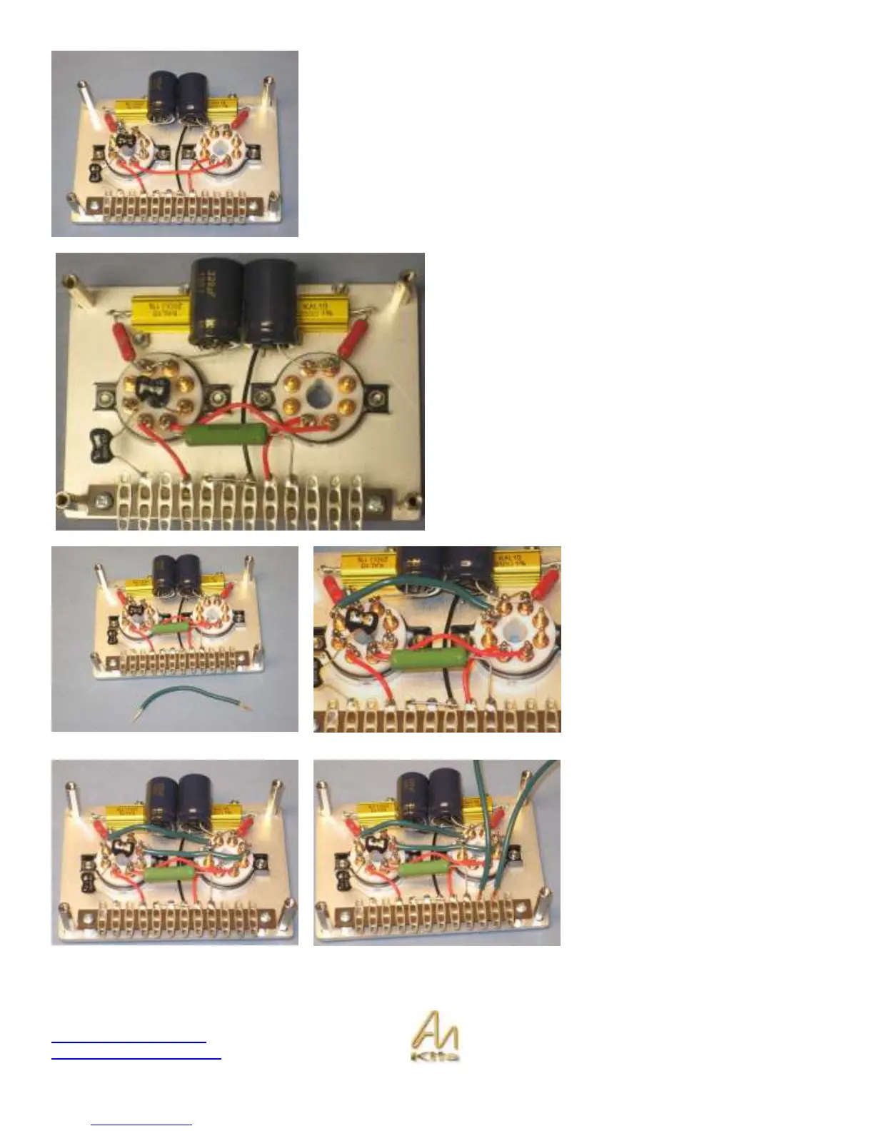
Use some red PTFE wire to connect pin 4 of one valve base to pin 4 of the other
base.
Connect the 470R 6W resistor into position (tag strip 4
position) with pin 4 of the left valve base.
That completes the component connection – now we will
finish up with the filament wiring.
We are now going to add the Filament
wire – the power supply will supply
6.3V AC voltage to this board via the
tag strip and this will connect to pins 2
& 7 of each EL34 – Lets start this
wiring by “paralleling” the pins 2 & 7 of
the two valve bases.
Start by cutting a short piece of the
green 16Guage wire and connecting
between pin 7 and pin 7 of each valve
base.
Do the same for pin 2 of each valve
base. It is preferable if you twist the
wire.
Then add the green filament wire to
the positions 2 & 3 on the tag strip –
cut off some strips of wire and solder
into position.