4. Assembly
4.1 Mounting position
AUMA actuators and actuator controls can be operated without restriction in any
mounting position.
4.2 Handwheel fitting
Information For transport purposes, handwheels from a diameter of 400 mm are supplied sepa-
rately.
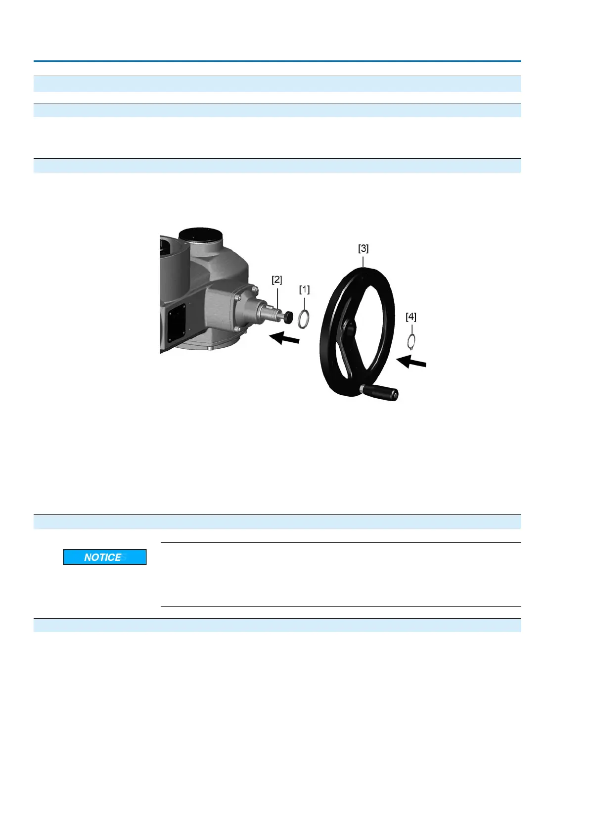
Figure 5: Handwheel
[1] Spacer
[2] Input shaft
[3] Handwheel
[4] Circlip
1. If required, fit spacer [1] onto input shaft [2].
2. Slip handwheel [3] onto input shaft.
3. Secure handwheel [3] using the circlip [4] supplied.
4.3 Multi-turn actuator: mount to valve/gearbox
Danger of corrosion due to damage to paint finish and condensation!
→
Touch up damage to paint finish after work on the device.
→
After mounting, connect the device immediately to electrical mains to ensure
that heater minimises condensation.
4.3.1 Output drive types B, B1 – B4 and E
Application
●
For rotating, non-rising valve stem
●
Not capable of withstanding thrust
Design
Output drive bore with keyway:
●
Types B1 – B4 with bore according to ISO 5210
●
Types B and E with bore according to DIN 3210
●
Later change from B1 to B3, B4, or E is possible.
12
SA 07.2 – SA 16.2/SAR 07.2 – SAR 16.2 Control unit: electromechanic
Assembly AC 01.2 Intrusive

 Loading...


