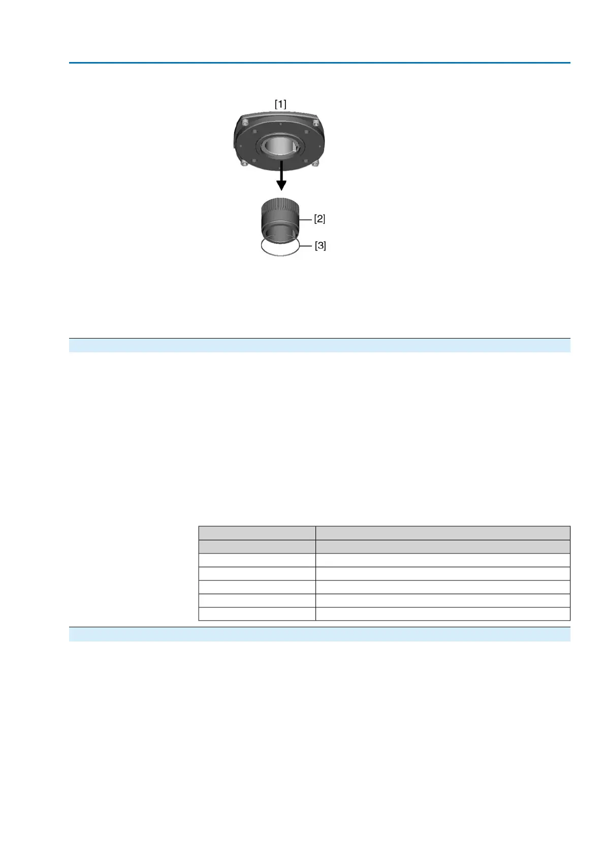
Figure 6: Output drive
[1] Output drive types B, B1 – B4, E and C
[2] Output drive sleeve/output drive plug sleve with bore and keyway
[3] Circlip
Information Spigot at flanges should be loose fit.
4.3.1.1 Multi-turn actuator (with output drive types B1 – B4 or E): mount to valve/gearbox
1. Check if mounting flanges fit together.
2. Check whether bore and keyway match the input shaft.
3. Apply a small quantity of grease to the input shaft.
4. Place multi-turn actuator.
Information: Ensure that the spigot fits uniformly in the recess and that the
mounting faces are in complete contact.
5. Fasten multi-turn actuator with screws according to table.
Information: We recommend applying liquid thread sealing material to the
screws to avoid contact corrosion.
6. Fasten screws crosswise to a torque according to table.
Table 2: Tightening torques for screws
Tightening torque T
A
[Nm]Screws
Strength class 8.8Threads
25M8
51M10
87M12
214M16
431M20
4.3.2 Output drive type A
Application
●
Output drive for rising, non-rotating valve stem
●
Capable of withstanding thrust
Information To adapt the actuators to output drive types A available on site with flanges F10 and
F14 (year of manufacture: 2009 and earlier), an adapter is required. The adapter
can be ordered from AUMA.
13
SA 07.2 – SA 16.2/SAR 07.2 – SAR 16.2 Control unit: electromechanic
AC 01.2 Intrusive Assembly

 Loading...


