2. If indicator disc [3] is available:
Remove indicator disc [3] using a spanner (as lever).
Information: To avoid damage to paint finish, use spanner in combination with
soft object, e.g. fabric.
Figure 62:
9.3 Torque switching: set
Once the set torque is reached, the torque switches will be tripped (overload protection
of the valve).
Information The torque switches may also trip during manual operation.
Valve damage due to excessive tripping torque limit setting!
→
The tripping torque must suit the valve.
→
Only change the setting with the consent of the valve manufacturer.
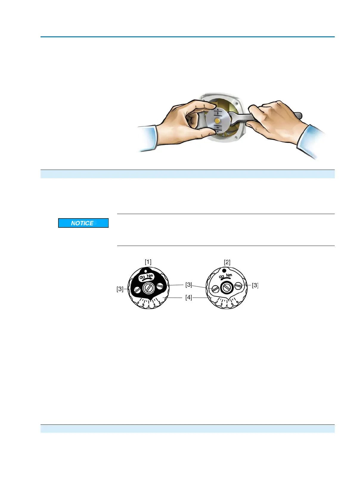
Figure 63: Torque switching heads
[1] Torque switching head black in direction CLOSE
[2] Torque switching head white in direction OPEN
[3] Lock screws
[4] Torque dials
1. Loosen both lock screws [3] at the indicator disc.
2. Turn torque dial [4] to set the required torque (1 da Nm = 10 Nm).
3. Fasten lock screws [3] again.
Information: Maximum tightening torque: 0.3 – 0.4 Nm
➥
The torque switch setting is complete.
Example: The figure above shows the following settings:
●
3.5 da Nm = 35 Nm for direction CLOSE
●
4.5 da Nm = 45 Nm for direction OPEN
9.4 Limit switching: set
The limit switching records the travel. When reaching the preset position, switches
are operated.
43
SA 07.2 – SA 16.2/SAR 07.2 – SAR 16.2 Control unit: electromechanic
AC 01.2 Intrusive Commissioning (basic settings)

 Loading...


