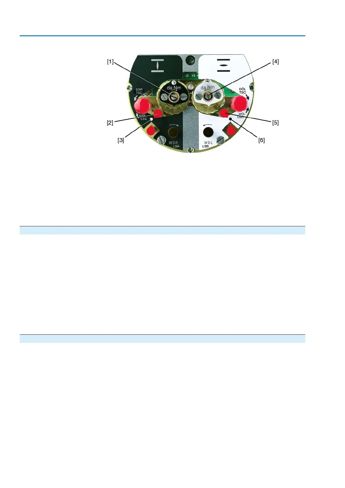
Figure 64: Setting elements for limit switching
Black section:
[1] Setting spindle: End position CLOSED
[2] Pointer: End position CLOSED
[3] Mark: End position CLOSED is set
White section:
[4] Setting spindle: End position OPEN
[5] Pointer: End position OPEN
[6] Mark: End position OPEN is set
9.4.1 End position CLOSED (black section): set
1. Engage manual operation.
2. Turn handwheel clockwise until valve is closed.
3. Turn handwheel by approximately half a turn (overrun) in the opposite direction.
4. Press down and turn setting spindle [1] with screw driver in direction of the
arrow and observe the pointer [2]: While a ratchet click is felt and heard, the
pointer [2] moves 90° every time.
5. If the pointer [2] is 90° from mark [3]: Continue turning slowly.
6. If the pointer [2] moves to mark [3]: Stop turning and release setting spindle.
➥
The end position CLOSED setting is complete.
7. If you override the tripping point inadvertently (ratchet click is heard after the
pointer has snapped): Continue turning the setting spindle in the same direction
and repeat setting process.
9.4.2 End position OPEN (white section): set
1. Engage manual operation.
2. Turn handwheel counterclockwise until valve is open.
3. Turn handwheel by approximately half a turn (overrun) in the opposite direction.
4. Press down and turn setting spindle [4] with screw driver in direction of the
arrow and observe the pointer [5]: While a ratchet click is felt and heard, the
pointer [5] moves 90° every time.
5. If the pointer [5] is 90° from mark [6]: Continue turning slowly.
6. If the pointer [5] moves to mark [6]: Stop turning and release setting spindle.
➥
The end position OPEN setting is complete.
7. If you override the tripping point inadvertently (ratchet click is heard after the
pointer has snapped): Continue turning the setting spindle in the same direction
and repeat setting process.
44
SA 07.2 – SA 16.2/SAR 07.2 – SAR 16.2 Control unit: electromechanic
Commissioning (basic settings) AC 01.2 Intrusive

 Loading...


