→
Operate actuator electrically (via the push buttons OPEN and CLOSE of the local
controls) once to end position OPEN and once to end position CLOSED.
9.7 Potentiometer setting
— Option —
The potentiometer as travel sensor records the valve position.
Information Due to the ratio of the reduction gearing the complete resistance range/stroke is not
always passed.Therefore, external adjustment (setting potentiometer) must be pro-
vided.
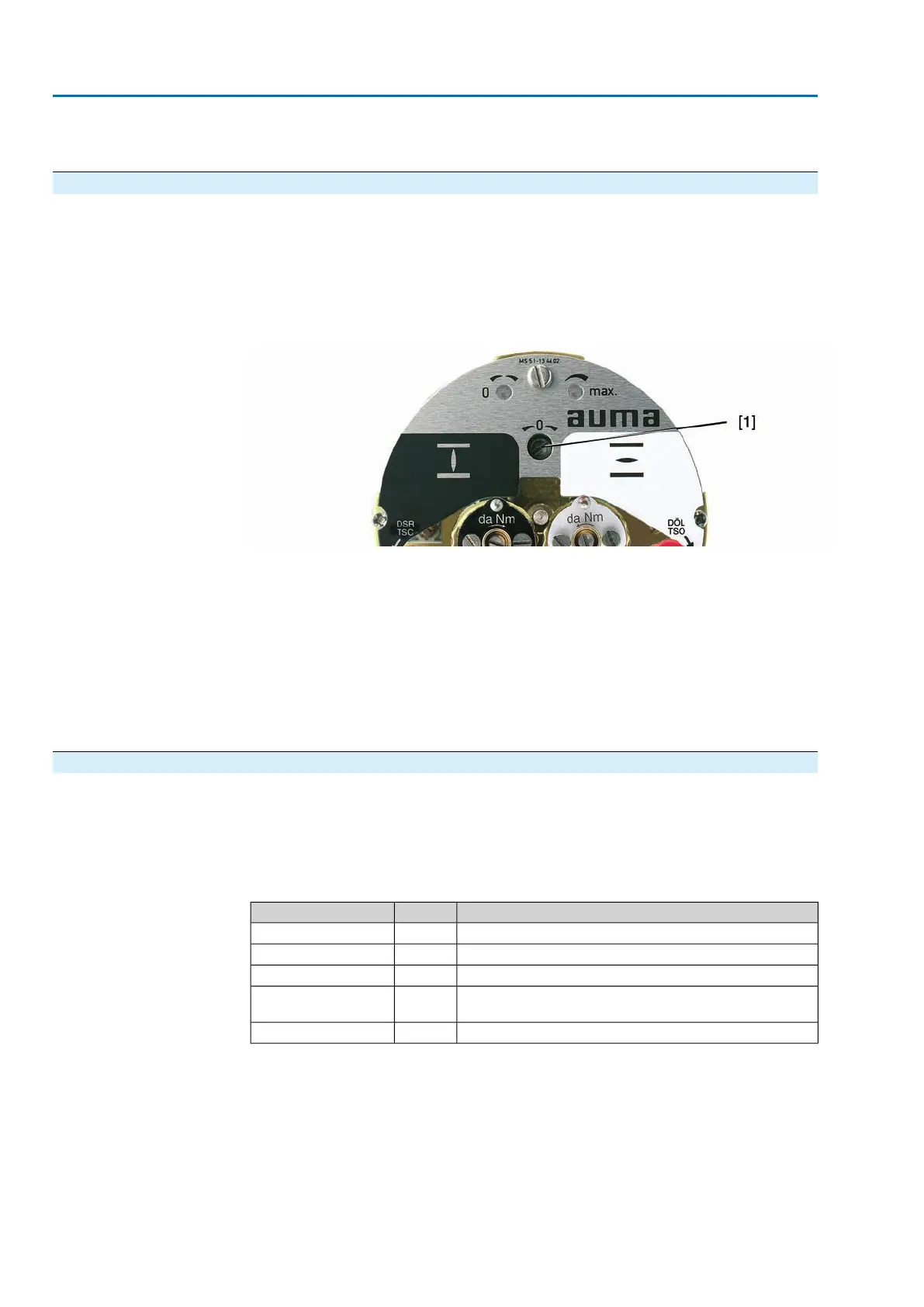
Figure 70: View of control unit
[1] Potentiometer
1. Move valve to end position CLOSED.
2. Turn potentiometer [1] clockwise to the stop.
➥
End position CLOSED corresponds to 0 %
➥
End position OPEN corresponds to 100 %
3. Turn potentiometer [1] slightly in opposite direction.
4. Perform fine-tuning of the zero point at external setting potentiometer (for remote
indication).
9.8 Electronic position transmitter RWG: set
— Option —
The electronic position transmitter RWG records the valve position. On the basis of
the actual position value measured by the potentiometer (travel sensor), it generates
a current signal between 0 – 20 mA or 4 – 20 mA.
Table 9: Technical data RWG 4020
3- or 4-wire systemWiring
9
th
position = E or HTPATerminal plan
0 – 20 mA, 4 – 20 mAI
A
Output current
24 V DC, ±15 % smoothedU
V
Power supply
24 mA at 20 mA output currentIMax. current consump-
tion
600 Ω
R
B
Max. load
48
SA 07.2 – SA 16.2/SAR 07.2 – SAR 16.2 Control unit: electromechanic
Commissioning (basic settings) AC 01.2 Intrusive

 Loading...


