5.2.3 Terminal compartment: close
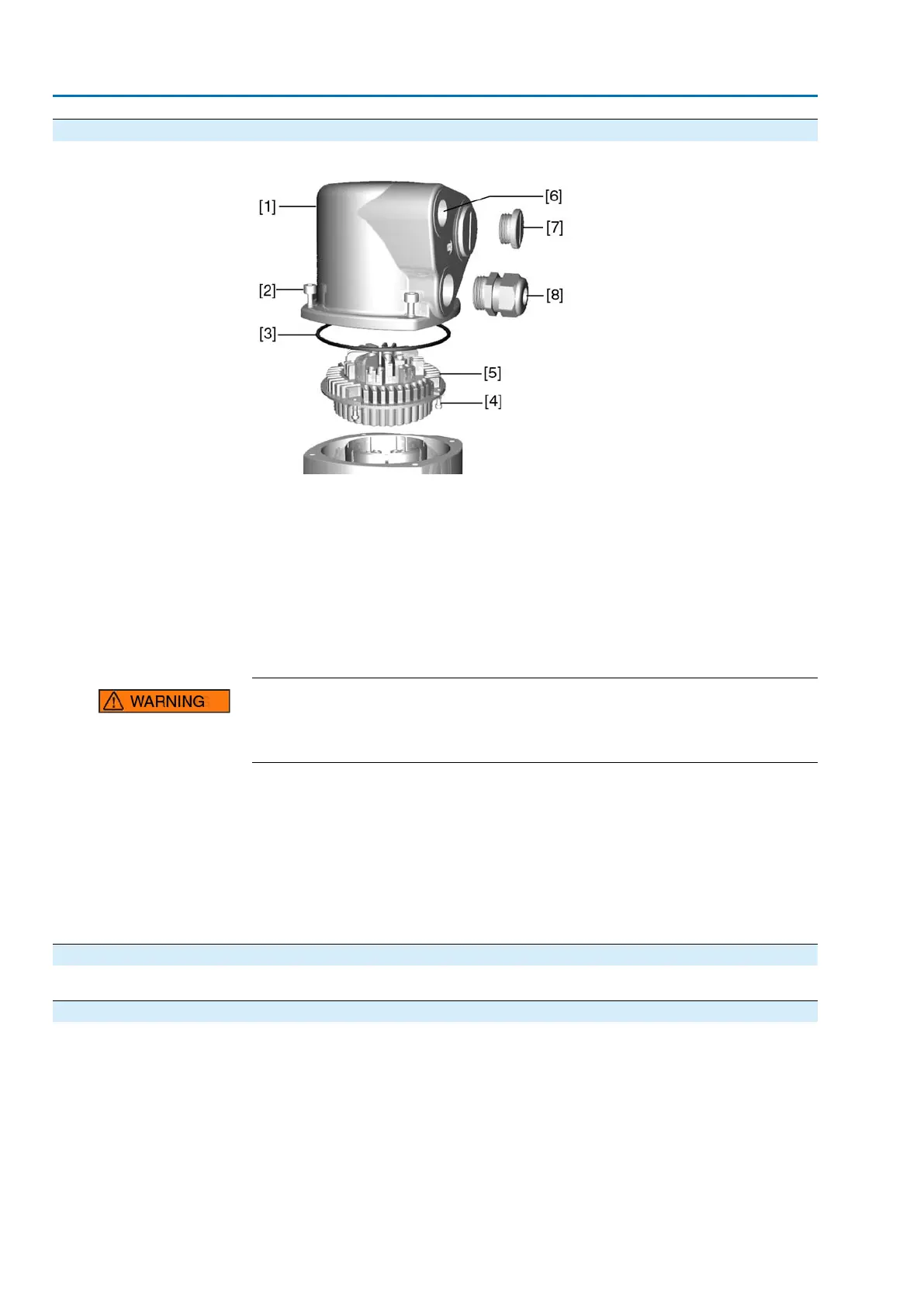
Figure 16: Example: Version S
[1] Cover
[2] Screws for cover
[3] O-ring
[4] Screws for socket carrier
[5] Socket carrier
[6] Cable entry
[7] Blanking plug
[8] Cable gland (not included in delivery)
Short-circuit due to pinching of cables!
Risk of electric shock and functional failures.
→
Carefully fit socket carrier to avoid pinching the cables.
1. Insert the socket carrier [5] into the cover [1] and fasten with screws [4].
2. Clean sealing faces of cover [1] and housing.
3. Check whether O-ring [3] is in good condition, replace if damaged.
4. Apply a thin film of non-acidic grease (e.g. petroleum jelly) to the O-ring and
insert it correctly.
5. Fit cover [1] and fasten screws [2] evenly crosswise.
6. Fasten cable glands [8] applying the specified torque to ensure the required
enclosure protection.
5.3 Accessories for electrical connection
— Option —
5.3.1 Controls mounted to wall bracket
The wall bracket allows separate mounting of controls and actuator.
Application
●
If the actuator cannot be accessed.
●
If the actuator is subjected to high temperatures.
●
In case of heavy vibration of the valve.
22
SA 07.2 – SA 16.2/SAR 07.2 – SAR 16.2 Control unit: electromechanic
Electrical connection AC 01.2 Intrusive

 Loading...


