5. Without the indicator disc:
→
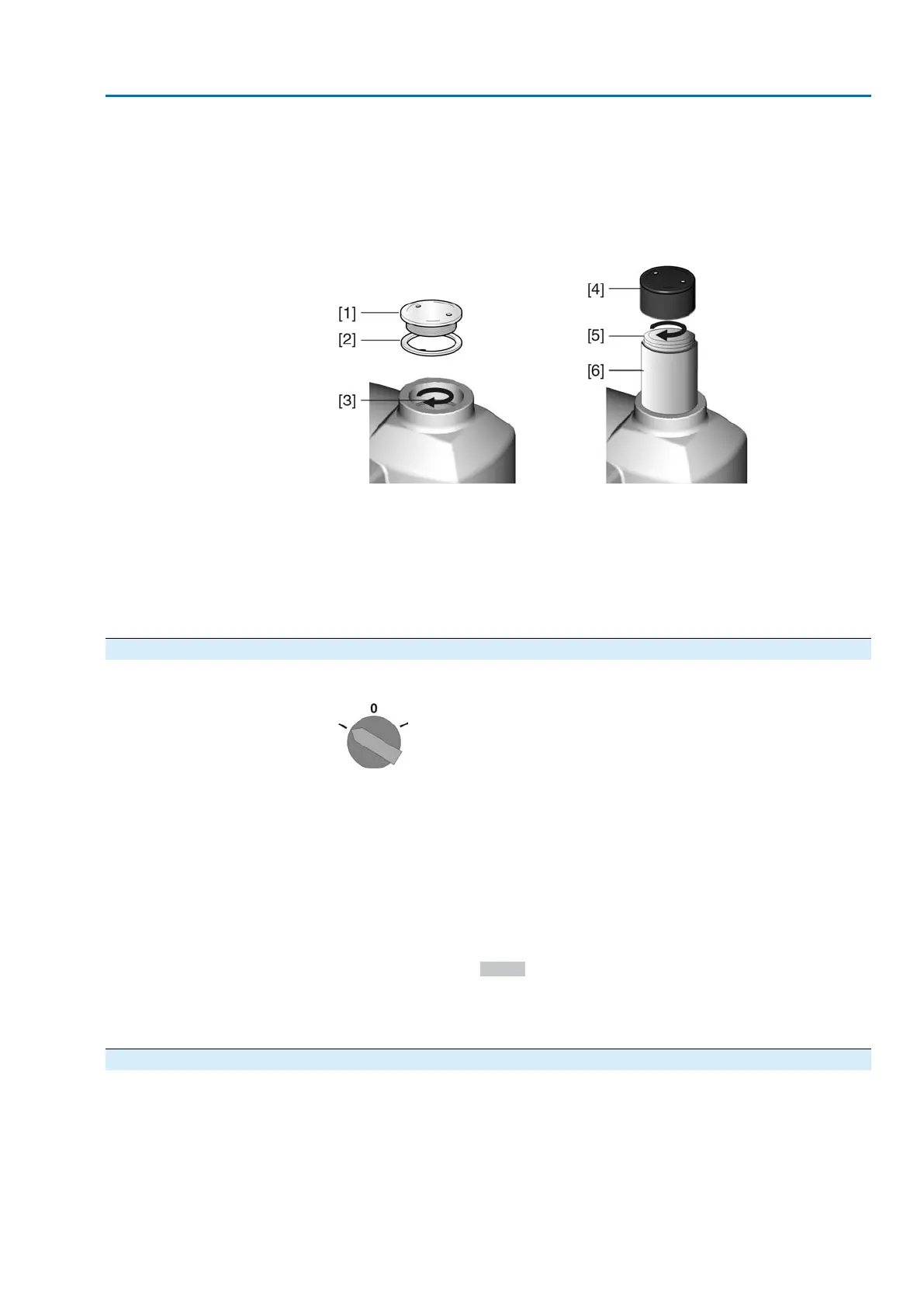
Unscrew threaded plug [1] and seal [2] or cap for stem protection tube [4]
and observe direction of rotation at hollow shaft [3] or the stem [5].
➥
The direction of rotation is correct, if actuator runs in direction CLOSE and
hollow shaft or stem turn clockwise.
Figure 68: Hollow shaft/stem
[1] Threaded plug
[2] Seal
[3] Hollow shaft
[4] Cap for stem protection tube
[5] Stem
[6] Stem protection tube
9.6.2 Limit switching: check
1. Set selector switch to position Local control (LOCAL).
2. Operate actuator using push buttons OPEN - STOP - CLOSE.
➥
The limit switching is set correctly if (default indication):
- the yellow indication light/LED1 is illuminated in end position CLOSED
- the green indication light/LED5 is illuminated in end position OPEN
- the indication lights go out after travelling into opposite direction.
➥
The limit switching is set incorrectly if:
- the actuator comes to a standstill before reaching the end position
- one of the red indication lights/LEDs is illuminated (torque fault)
-
the status indication S0007 in the display signals a fault.
3. If the end position setting is incorrect: Reset limit switching.
4. If the end position setting is correct and no options (e.g. potentiometer, position
transmitter) are available: Close switch compartment.
9.6.3 Reference operation position feedback: perform
For actuators with position feedback (RWG, potentiometer), a reference operation
has to be performed once the limit switching setting was changed to ensure that the
position feedback (0/4 – 20 mA) supplies correct values:
47
SA 07.2 – SA 16.2/SAR 07.2 – SAR 16.2 Control unit: electromechanic
AC 01.2 Intrusive Commissioning (basic settings)

 Loading...


