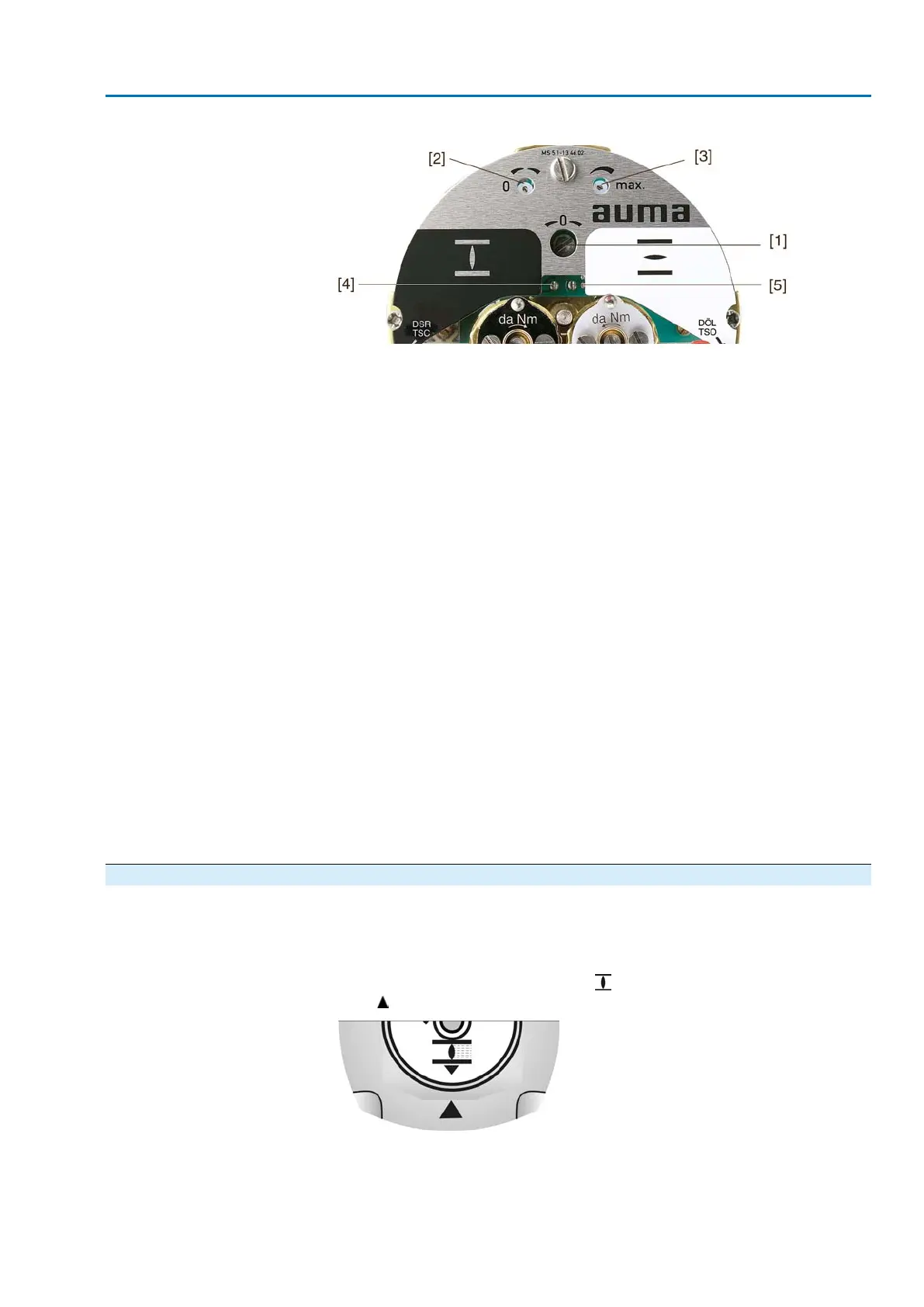
Figure 71: View of control unit
[1] Potentiometer (travel sensor)
[2] Potentiometer min. (0/4 mA)
[3] Potentiometer max. (20 mA)
[4] Measuring point (+) 0/4 – 20 mA
[5] Measuring point (–) 0/4 – 20 mA
1. Connect voltage to electronic position transmitter.
2. Move valve to end position CLOSED.
3. Connect ammeter for 0 – 20 mA to measuring points [4 and 5].
4. Turn potentiometer [1] clockwise to the stop.
5. Turn potentiometer [1] slightly in opposite direction.
6. Turn potentiometer [2] clockwise until output current starts to increase.
7. Turn potentiometer [2] in opposite direction until the following value is reached:
- for 0 – 20 mA approx. 0.1 mA
- for 4 – 20 mA approx. 4.1 mA
➥
This ensures that the signal remains above the dead and live zero point.
8. Move valve to end position OPEN.
9. Set potentiometer [3] to end value 20 mA.
10. Approach end position CLOSED again and check minimum value (0.1 mA or
4.1 mA). If necessary, correct the setting.
Information If the maximum value cannot be reached, the selection of the reduction gearing must
be checked. (The max. possible turns/stroke are indicated on the order-related
technical data sheet for the actuator.)
9.9 Mechanical position indicator: set
— Option —
1. Place indicator disc on shaft.
2. Move valve to end position CLOSED.
3.
Turn lower indicator disc until symbol (CLOSED) is in alignment with the
mark on the cover.
4. Move actuator to end position OPEN.
49
SA 07.2 – SA 16.2/SAR 07.2 – SAR 16.2 Control unit: electromechanic
AC 01.2 Intrusive Commissioning (basic settings)

 Loading...


