5.2.1 Terminal compartment: open
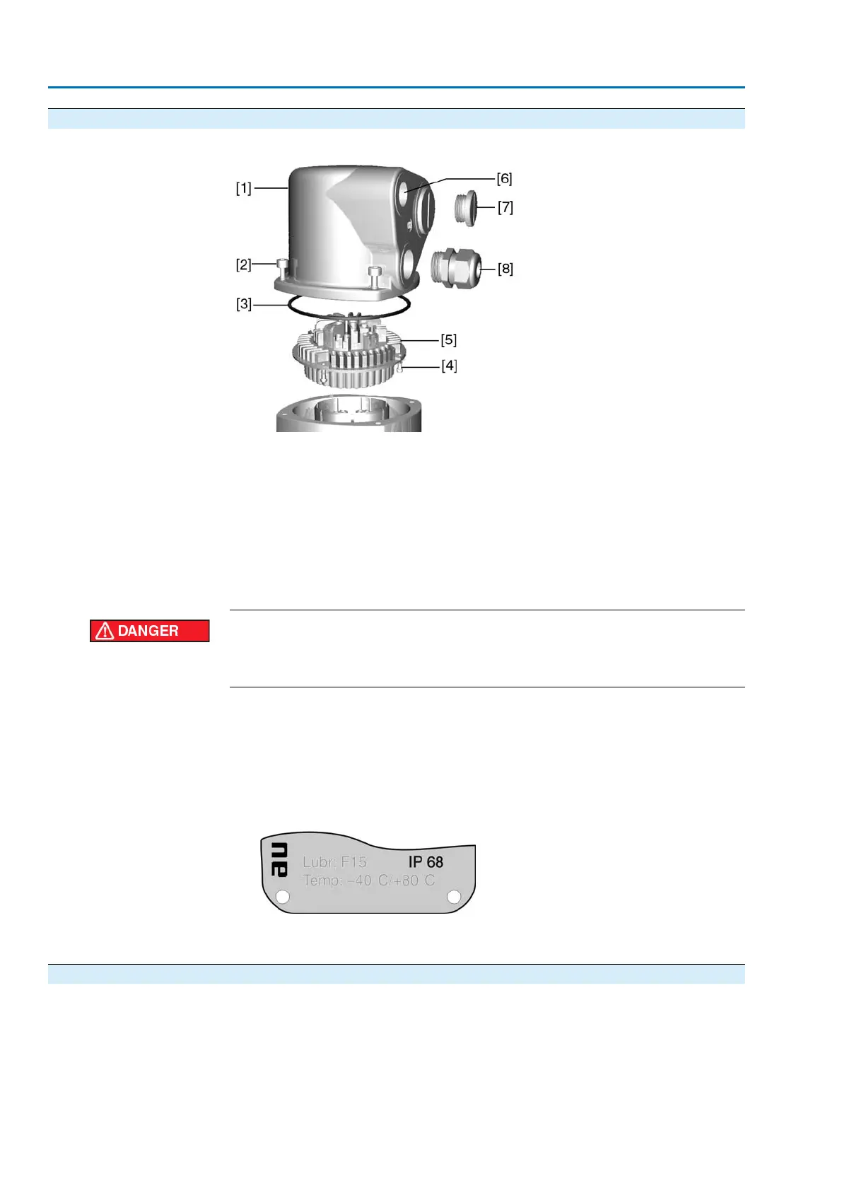
Figure 13: Connection AUMA plug/socket connector, version S
[1] Cover
[2] Screws for cover
[3] O-ring
[4] Screws for socket carrier
[5] Socket carrier
[6] Cable entry
[7] Blanking plug
[8] Cable gland (not included in delivery)
Hazardous voltage!
Risk of electric shock.
→
Disconnect device from the mains before opening.
1. Loosen screws [2] and remove cover [1].
2. Loosen screws [4] and remove socket carrier [5] from cover [1].
3. Insert cable glands [8] suitable for connecting cables.
➥
The enclosure protection IP... stated on the name plate is only ensured if suitable
cable glands are used. Example: Name plate shows enclosure protection IP
68.
4. Seal unused cable entries [6] with suitable blanking plugs [7].
5. Insert the cables into the cable glands [8].
5.2.2 Cable connection
✔
Observe permissible cross sections.
1. Remove cable sheathing.
2. Strip wires.
3. For flexible cables: Use end sleeves according to DIN 46228.
4. Connect cables according to order-related wiring diagram.
20
SA 07.2 – SA 16.2/SAR 07.2 – SAR 16.2 Control unit: electromechanic
Electrical connection AC 01.2 Intrusive

 Loading...


