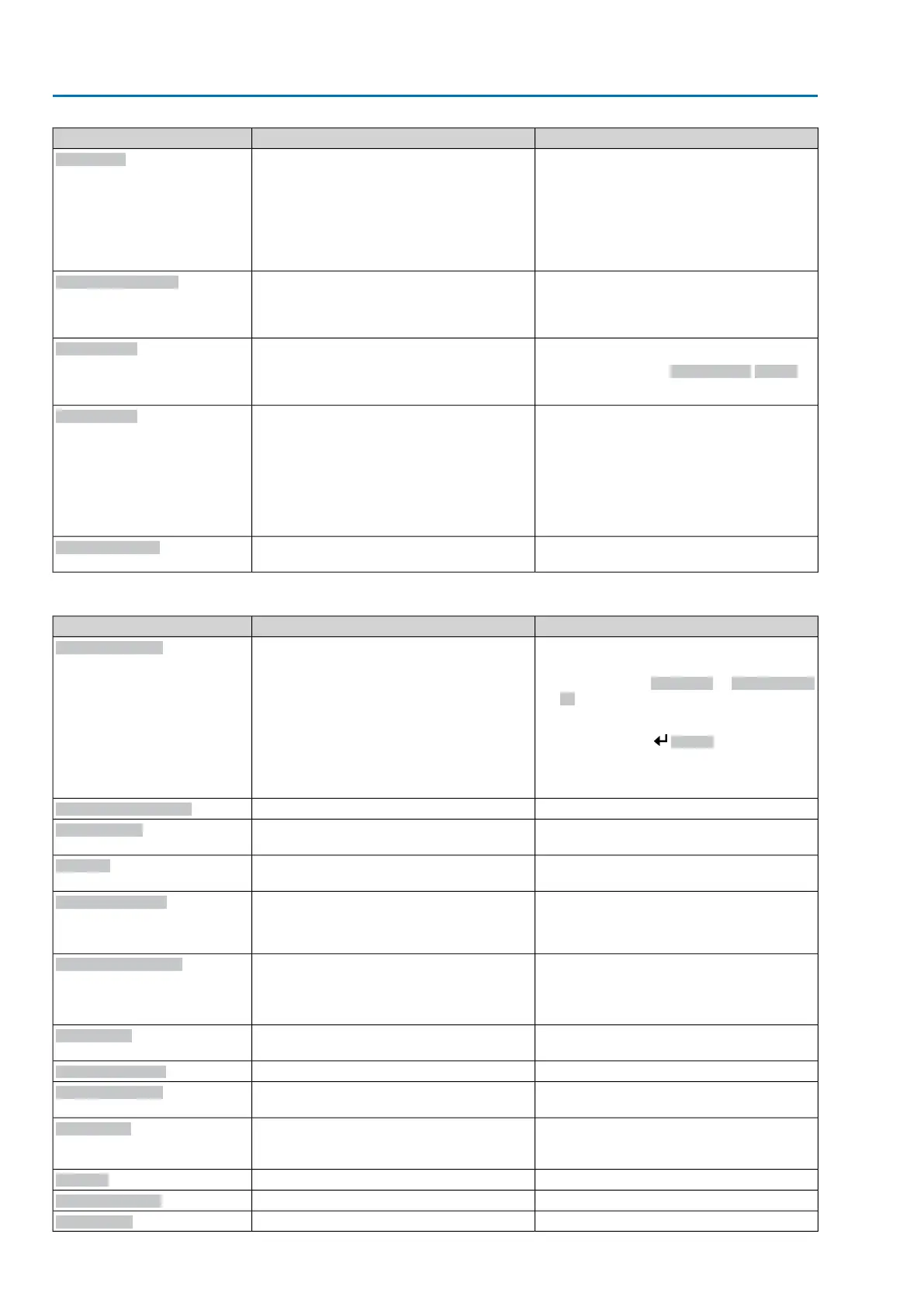
RemedyDescription/causeIndication on display
Test/connect phases.
●
When connecting to a 3-ph AC system and
with internal 24 V DC supply of the electro-
nics: Phase 2 is missing.
●
When connecting to a 3-ph or 1-ph AC
system and with external 24 V DC supply
of the electronics: One of the phases L1,
L2 or L3 is missing.
Phase fault
Correct the sequence of the phase conductors
L1, L2 and L3 by exchanging two phases.
The phase conductors L1, L2 and L3 are
connected in the wrong sequence.
Only applicable if connected to a 3-ph AC
system.
Incorrect phase seq
●
Check mains voltage.
●
Check parameter Tripping time M0172,
extend time frame if required.
Due to insufficient mains quality, the controls
cannot detect the phase sequence (sequence
of phase conductors L1, L2 and L3) within the
pre-set time frame provided for monitoring.
Mains quality
●
Cool down, wait.
●
If the fault indication display persists after
cooling down:
-
Set selector switch to position Local
control (LOCAL) and reset fault indica-
tion via push button RESET.
●
Check fuses.
Motor protection tripped
Thermal fault
Check movement at actuator.No actuator reaction to operation commands
within the set reaction time.
Fault no reaction
Table 14: Not ready REMOTE and Function check (collective signal 04)
RemedyDescription/causeIndication on display
●
Check operation commands (send one
operation command only).
●
Set parameter Positioner to Function acti-
ve.
●
Check setpoint.
Press push button Details to display a list
of individual indications.
For a description of the individual signals, refer
to Manual (Operation and setting).
Collective signal 13:
Possible causes:
●
Several operation commands (e.g. OPEN
and CLOSE simultaneously, or OPEN and
SETPOINT operation simultaneously)
●
A setpoint is present and the positioner is
not active
●
For fieldbus: Setpoint exceeds 100.0 %
Wrong oper. cmd
Set selector switch to position REMOTE.Selector switch is not in position REMOTE.
Sel. sw. not REMOTE
Exit service software.Operation via service interface (Bluetooth) and
service software AUMA ToolSuite.
Service active
Check setting and status of function <Local
controls enable>.
Actuator is in operation mode Disabled.
Disabled
●
Enable EMERGENCY stop switch.
●
Reset EMERGENCY stop state by means
of Reset command.
The EMERGENCY stop switch has been
operated.The motor control power supply
(contactors or thyristors) is disconnected.
EMCY stop active
●
Detect cause for EMERGENCY signal.
●
Verify failure source.
●
Apply +24 V DC at EMERGENCY input.
Operation mode EMERGENCY is active
(EMERGENCY signal was sent).
0 V are applied at the EMERGENCY input.
EMCY behav. active
Check I/O interface.The actuator is controlled via the I/O interface
(parallel).
I/O interface
Start motor operation.Manual operation is activated.
Handwheel active
Verify master configurationFieldbus connection available, however no
process data transmission by the master.
FailState fieldbus
Release push button STOP.A local STOP is active.
Push button STOP of local controls is opera-
ted.
Local STOP
Check interlock signal.An interlock is active.
Interlock
Check states of main and by-pass valve.By-pass function is interlocked.
Interlock by-pass
Wait until PVST function is complete.Partial Valve Stroke Test (PVST) is active.
PVST active
54
SA 07.2 – SA 16.2/SAR 07.2 – SAR 16.2 Control unit: electromechanic
Corrective action AC 01.2 Intrusive

 Loading...


