1 Product Introduction
22 © Copyright Reserved Autonics Co., Ltd.
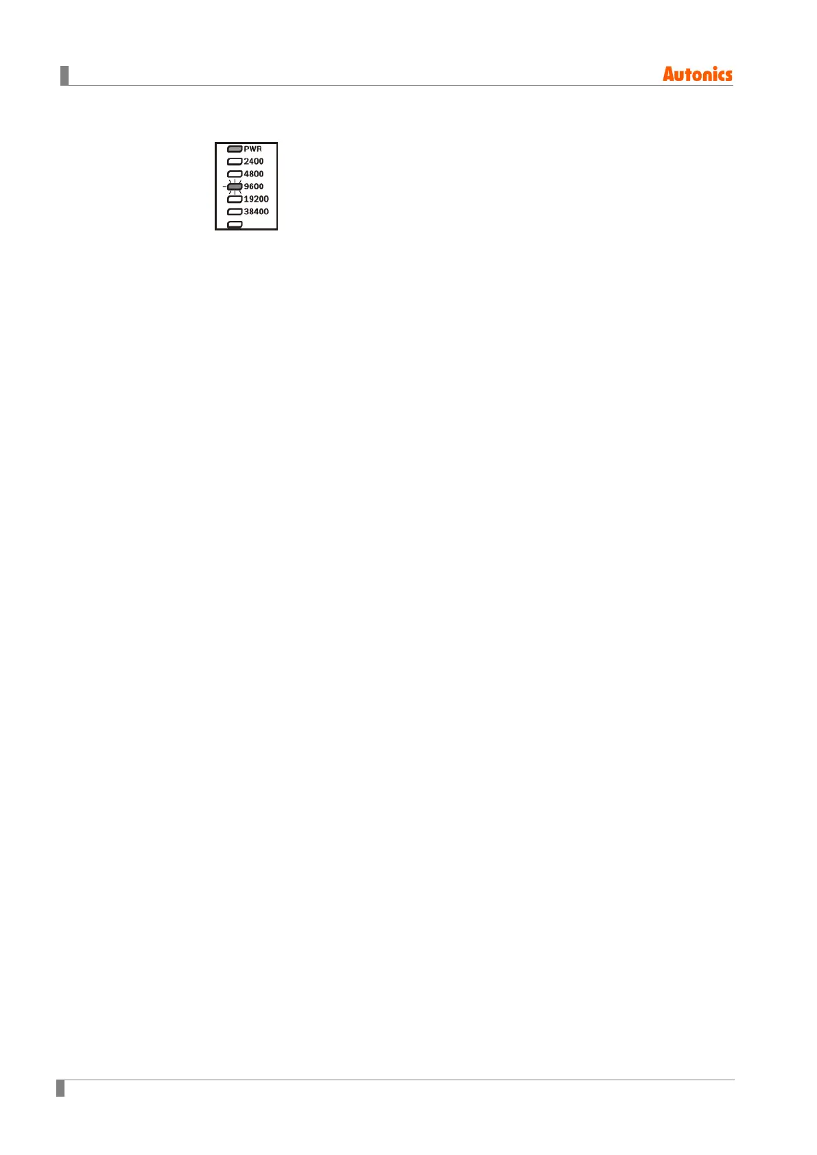
※1. When power is supplied initially, the set communication speed LED flashes for 5 sec.
※2. The auto-tuning CH□ LED flashes for 1 sec in turn.
※3. The PWR LED flashes during communication for 1 sec in turn.
※4. Turns ON when CH1 control method is heating & cooling control and cooling output occurs.
(disable AL1 setting)
※5. Turns ON when CH2 control method is heating & cooling control and cooling output occurs.
(disable AL2 setting)
⑦ Communication address setting switch (SW1): Set the communication address.
⑧ Communication address group switch (SW2): When setting the communication address
over 16, select +16.
⑨ Lock switch: Used for fixing modules at top and bottom.
⑩ Rail Lock: Used for installing at DIN rail or using bolts.
⑪ END cover: Remove it when connecting each module to connect an expansion connector.
 Loading...