6 Parameter Settings and Functions
© Copyright Reserved Autonics Co., Ltd. 77
6.5 Communications
This feature is used for external higher systems (PC, GP, etc.) to set the controller's parameters
and to monitor the controller. It can also be used to external devices.
No redundant unit addresses may exist along the same communication line.
The communication cable must be twisted pair that supports RS485.
(1) Interface
Comm. protocol Modbus RTU
Connection type RS485
Application standard Compliance with EIA RS485
Max. connection 31 units (address: 01 to 31)
Synchronous method Asynchronous
Comm. method Two-wire half duplex
Comm. method Max. 800m
Comm. speed 2400, 4800, 9600(default), 19200, 38400
Start bit 1-bit (fixed)
Data bit 8-bit (fixed)
Parity bit None(default), Even, Odd
Stop bit 1-bit, 2-bit (default)
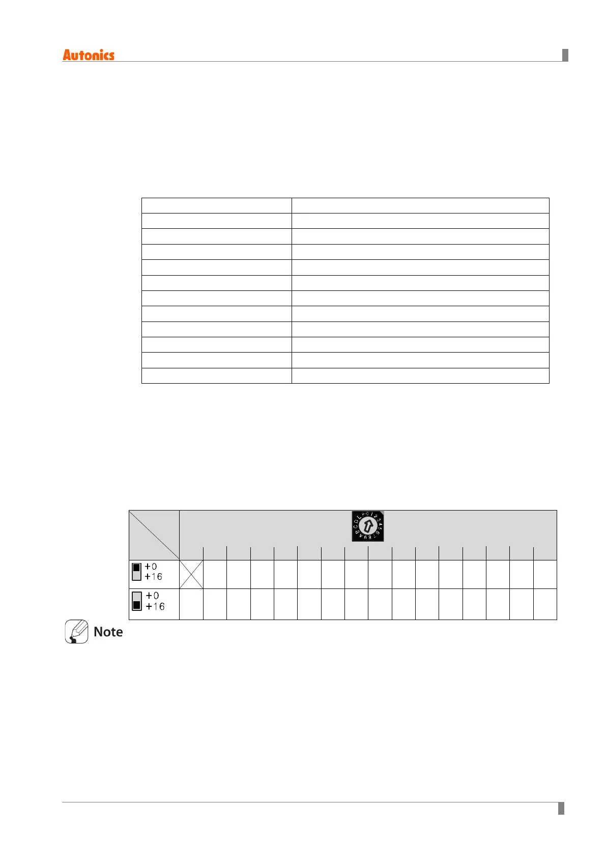
6.5.1 Communication address
You can assign a unique address to each device.
Users can set communication address using both SW1 (communication address setting switch)
and SW2 (communication group change switch).
Setting range: 01 to 31
Factory default: [SW1] 1, [SW2] +0
00 01 02 03
05 06 07 08
11 12 13 14
16 17 18 19
21 22 23 24
27 28 29 30
If 00 is designated, communications are not performed.
SW2
SW1
 Loading...