24
400 SeriesOperating instructions
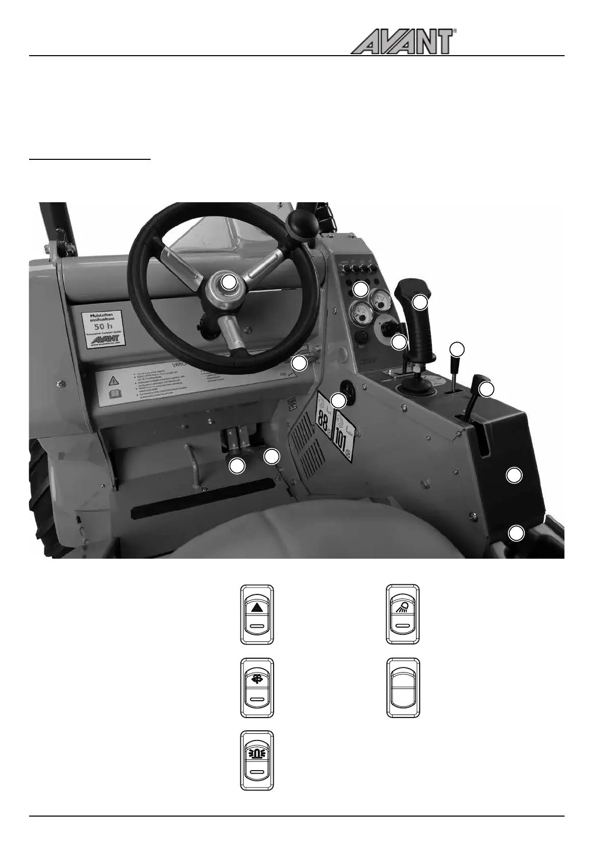
1. Steering wheel
2. Drive pedal, left: drive backward
3. Drive pedal, right: drive forward
4. Parking brake handle
5. Control lever of boom and bucket
6. Hand throttle lever
7. Auxiliary hydraulics control lever
8. Control lever of telescopic boom
9. 12 V outlet (max 15 A).
Cab LX/DLX see page 26
10. Dashboard, see page 26
11. Hour meter
12. Switches on the panel
Work light
(option)
Emergency
blinker
(option)
Windscreen
wiper and
washer
(Cab option)
Beacon
(option)
2
1
Front/rear auxi-
liary hydraulics
selector switch
(option)
Operating instructions
2
1
3
5
6
7
8
11
12
10
4
9
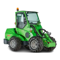
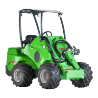
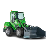
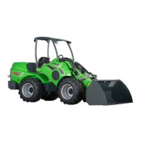
Operating controls
Following picture shows the location of operating controls. The location and function
of controls may be slightly different in different models, see following pages.