Installing and Cabling the Cabinets
54 Installation, Upgrades and Additions for Avaya CMC1 Media Gateways
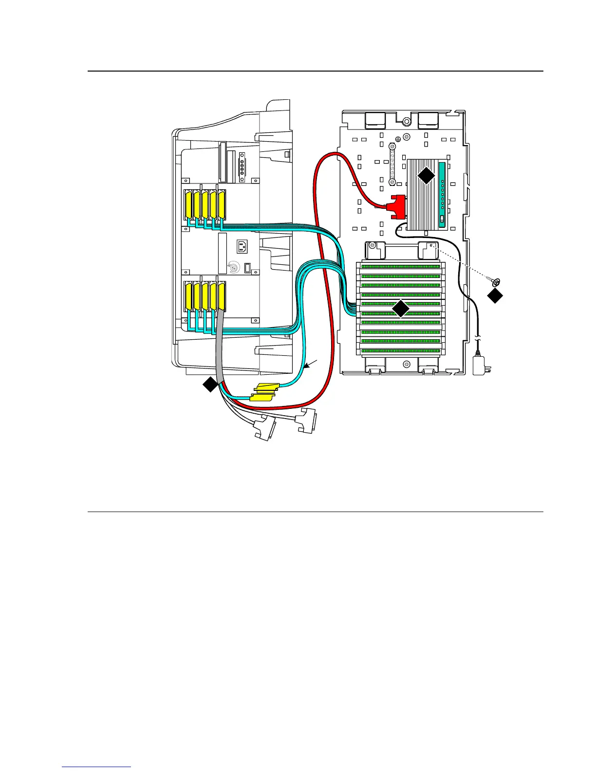
Figure 16: Typical Bottom-Mount MDF and Modem Cable Routing
Figure notes:
1. Main distribution frame (MDF)
2. External modem
3. Processor interface cable (connect P2 to
modem, connect J1 to cable 1 on MDF)
4. #12 x 1-inch shoulder screw
cadmrpnl KLC 070698
1
1
2
5
6
7
8
4
3
9
10
3
1
2
4
10
10
9
9
8
8
7
7
6
6
5
5
4
4
3
3
2
2
1
1


 To Next Page