Connection Purpose
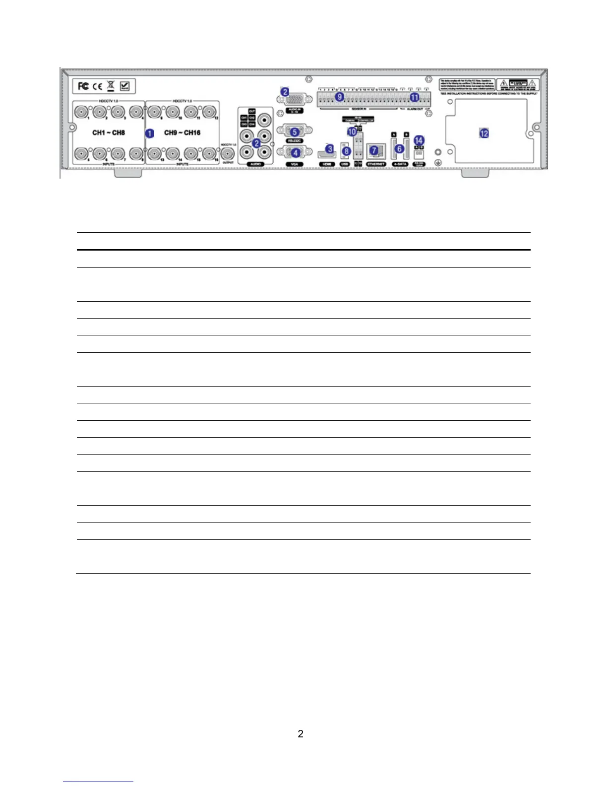
1
VIDEO IN
HD-SDI
connectors for video input.
2
AUDIO IN
4/8/16 connectors for audio input.
In case of 16ch, an audio cable is needed from ch 5 to ch 16.
AUDIO OUT
1 connector for audio output.
3
HDMI OUT
HDMI
connectors for main video output.
4
VGA
Connector for VGA monitor.
5
RS-232C
For engineering use only, the function be used by a gender through the
VGA output
6
E-SATA
External SATA terminal
7
ETHERNET
RJ-45 connector for network function
8
USB Port
Connector for Mouse or Backup
9
SENSOR IN
4/8/16 Connectors for Sensor device connection
10
RS-485
RS-485 control terminal (D+, D-)
11
ALARM OUT
1/2/4 connectors for alarm device.
Provide simple on/off switching by using relay (A, B)
12
POWER
DV12V for 4/8ch. 280W SMPS for 16ch
13
Cooling FAN
14
TERMINATE
RS-485 termination switch for 1
st
and 2
nd
for 16ch.
Switch On: Termination. Switch Off: No Termination