52
Model E1010 Indicator Service Manual
OUTPUT
(Output test)
INPUT
(Input test)
Supervisor Menu—TEST submenu (continued)
12. Press the UNITS key…
SERIAL is displayed. This is the serial port test item.
13. Press the PRINT key…
PORT1 is displayed.
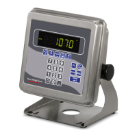
14. Use the TARE or UNITS keys to toggle between Port 1 and Port 2. To
test the communications port, jumper the TX and RX lines (pins 2 and 3
as shown in illustration at left). When the port you want to test is dis-
played, press the PRINT key…
With the pins jumpered, if the wiring and hardware are operating
correctly, PASS will be displayed. If there is a problem, FAIL will
be displayed and you should contact a service representative.
15. Press SELECT key to exit the serial test.
SERIAL is displayed.
16. Press the UNITS key…
INPUT is displayed. This will test remote input switches connected
to the indicator.
17. Press the PRINT key to access the test.
1 2 3 is displayed. 1 stands for input 1, etc.
18. Activate any remote switches connected to the indicator to verify hard-
ware and wiring…
The display will show the input number change to 0 if the external
switch is operating properly.
19. Press the SELECT key to exit the test…
INPUT is displayed.
20. Press the UNITS key…
OUTPUT is displayed. This is the output test item. See note at
left.
21. Press the PRINT key to access the test.
OUT 1 is displayed. This stands for output 1.
22. Press the PRINT key…
The display toggles between ON and OFF. This will toggle the
output off and on. Use a Trips Interface Unit (TIU3) or other output
device. Monitor the output to see that it is turning on and off.
23. Stop the test by pressing the SELECT key…
OUT 1 is displayed.
24. Press the UNITS key…
OUT 2 is displayed.
SERIAL
(Serial port test)
CAUTION: Follow all lockout
and red tag procedures.
Disconnect all devices not
intended to start before
running this test.

 Loading...