18 XR Series Installation Instructions
4 Wiring
RS 232 Daisy Chain / Multi-Drop Wiring
RS 422/485 Wiring
Terminate the indicator’s communication wires at the RS 485 terminal (J4), shown in
Figure 4.1.
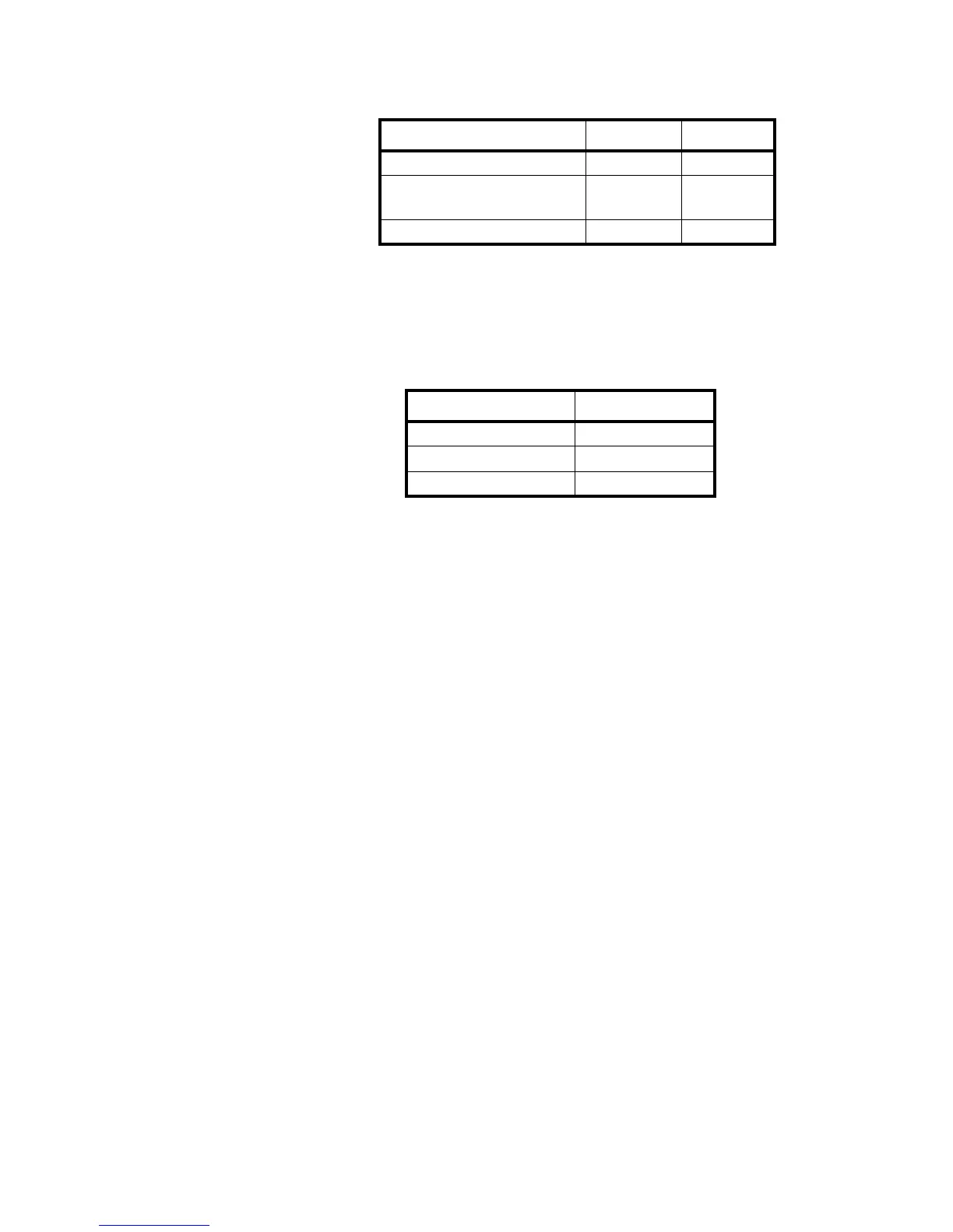
See the table below for pin assignments:
INDICATOR TO RD 1 TO RD 2
TX RX
No connection for Daisy Chain.
RX for Multi-drop.
TX RX
GND GND GND
INDICATOR TO XR
TRANSMIT A (TX A) RECEIVE A (RX A)
TRANSMIT B (TX B) RECEIVE B (RX B)
SIGNAL GROUND SIGNAL GROUND

 Loading...