XR Series Installation Instructions 17
4.1 Wiring the XR 4500, 4500TL or 6500
4Wiring
4.1 Wiring the XR 4500, 4500TL or 6500
4.1.1 Power Wiring
XR displays are wired for power at the factory. The factory supplied power cable can
be removed for direct AC wiring if necessary.
4.1.2 Communications Wiring
All communications wiring terminates at the controller board. Communications should
be wired before applying power to the unit.
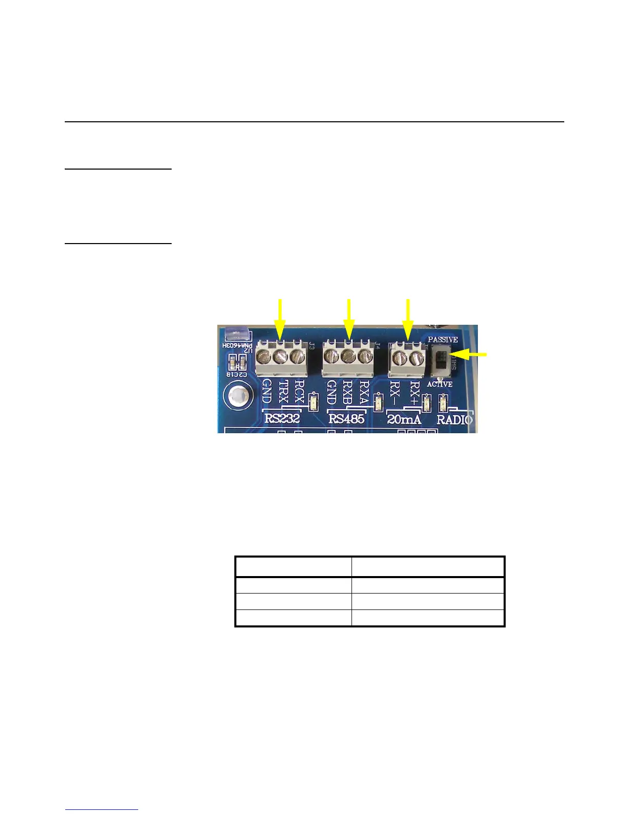
Figure 4.1 Communication terminals
RS 232 Wiring
Terminate the indicator’s communication wires at the RS 232 terminal (J3), shown in
Figure 4.1.
See the table below for pin assignments:
J3 J4 J5
20mA
Mode
Switch
(SW10)
INDICATOR TO XR
TRANSMIT (TX) RECEIVE (RX)
RECEIVE (RX) NO CONNECTION
SIGNAL GROUND (GND) SIGNAL GROUND (SIG GND)
 Loading...