20 XR Series Installation Instructions
4 Wiring
20mA Current Loop Wiring
Terminate the indicator’s communication wires at the 20mA Current Loop terminal (J5),
shown in Figure 4.1.
See table below for pin assignments:
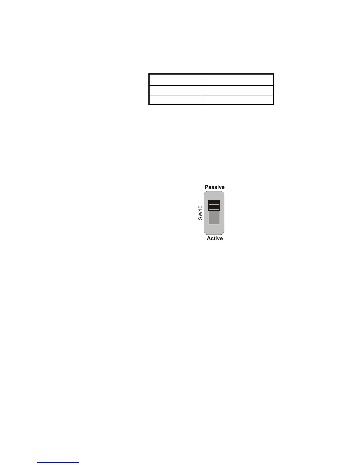
20mA Current Loop Mode Switch
l After the current loop is wired, ACTIVE or PASSIVE mode must be selected
(SW 10) on the controller board. See Figure 4.2.
l Select Active mode if the XR is required to supply the current to the
communicating device.
l Select Passive mode if the communicating device (indicator) supplies the
current to the XR.
Figure 4.2 20mA Mode Switch
INDICATOR TO XR
20 mA TX + RECEIVE POSITIVE (RX +)
20 mA TX - RECEIVE NEGATIVE (RX -)
 Loading...