XR Series Installation Instructions 39
7.6 CONFIG Switches (XR 2000)
Switches 4 & 5: Multi-Drop ID
Up to four (4) XR displays can share a serial or radio connection. Messages are sent
to individual displays using control codes and these Multi-Drop IDs. For Multi-Drop
instructions, see Multi-Drop addressing on page 48.
Switches 6 & 7: Radio Channel Select
The 900 MHz Radio Module (optional) has 4 frequency channels. If there are multiple
scale/remote display installations at a given site, each installation must have its own
radio channel selected.
If the wireless connection experiences interference problems from another radio site,
switching radio channels will most likely correct the problem.
The XR 2000 remote display must be configured with the same radio channel as the
wireless transceiver connected to the indicator. See Wireless Set-up for All XR Models
on page 24.
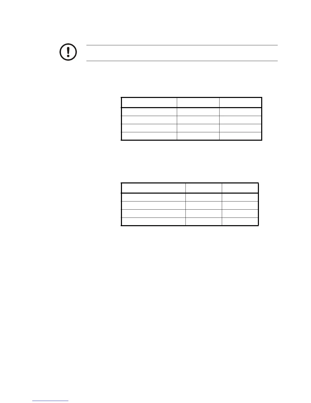
If Multi-Drop is not being used, it is very important that Switches 4 & 5 be set in
the OFF position.
MULTI-DROP I.D. SWITCH 4 SWITCH 5
0 (Default) OFF OFF
1ONOFF
2OFFON
3ONON
RADIO CHANNEL SWITCH 6 SWITCH 7
0 (Default) OFF OFF
1ONOFF
2OFFON
3ONON
 Loading...