Connecting to External Devices
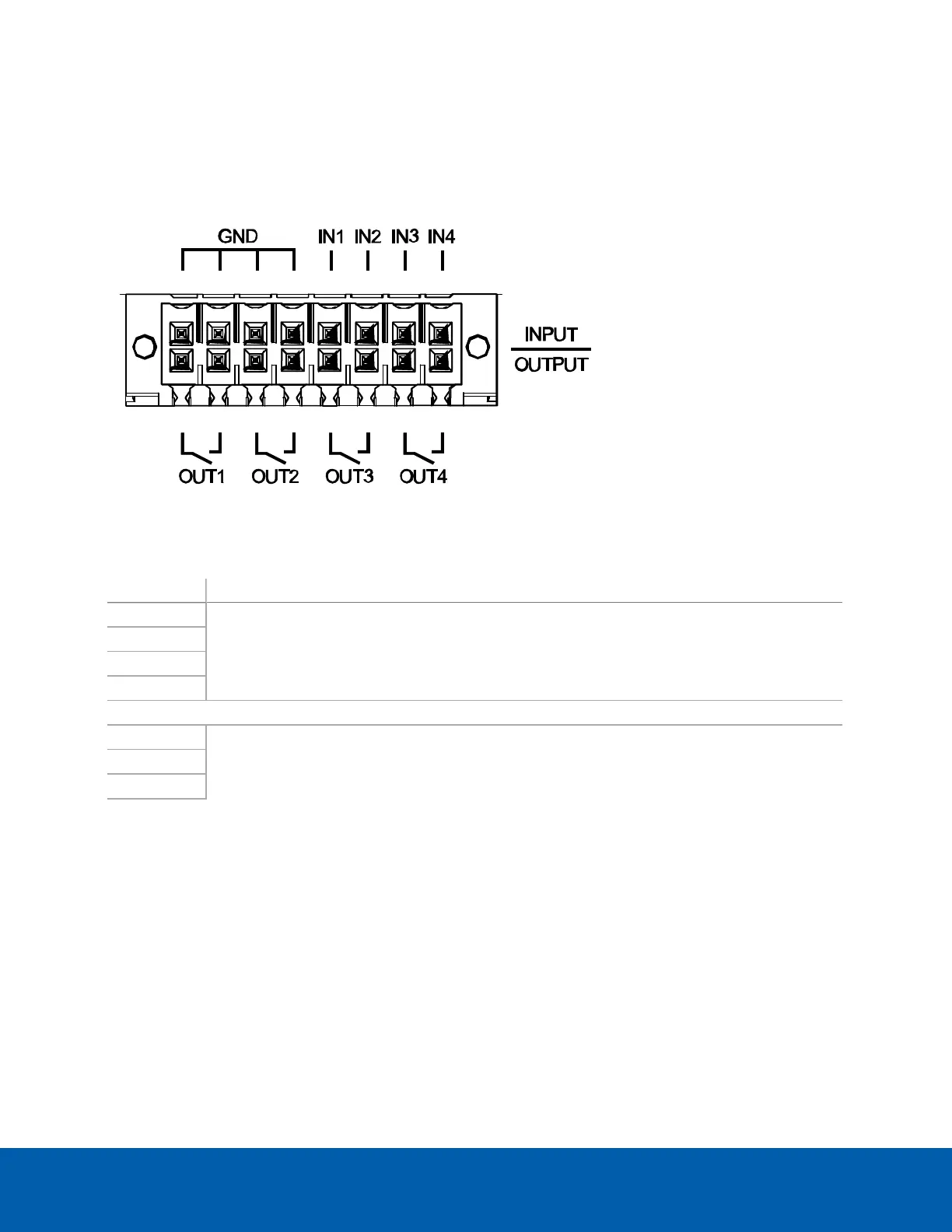
External devices are connected to the appliance through the I/O terminal. The pinout for the I/O terminal is
shown in the following diagram:
Figure 1: The ENVR2 Plus Appliance I/O pins are shown in the image above.
Function Description
IN1
Alarm Inputs— Active-Low inputs. To activate, connect the Input to the Ground pin (GND). To
deactivate, leave disconnected.
IN2
IN3
IN4
GND
OUT1
Relay Outputs — Form-A dry contact outputs. When active, terminals are connected. When
inactive, terminals are disconnected.
Maximum load of each relay output: 1A at 30 V DC; 0.3 A at 125 V AC.
OUT2
OUT3
OUT4
Connecting to External Devices 30