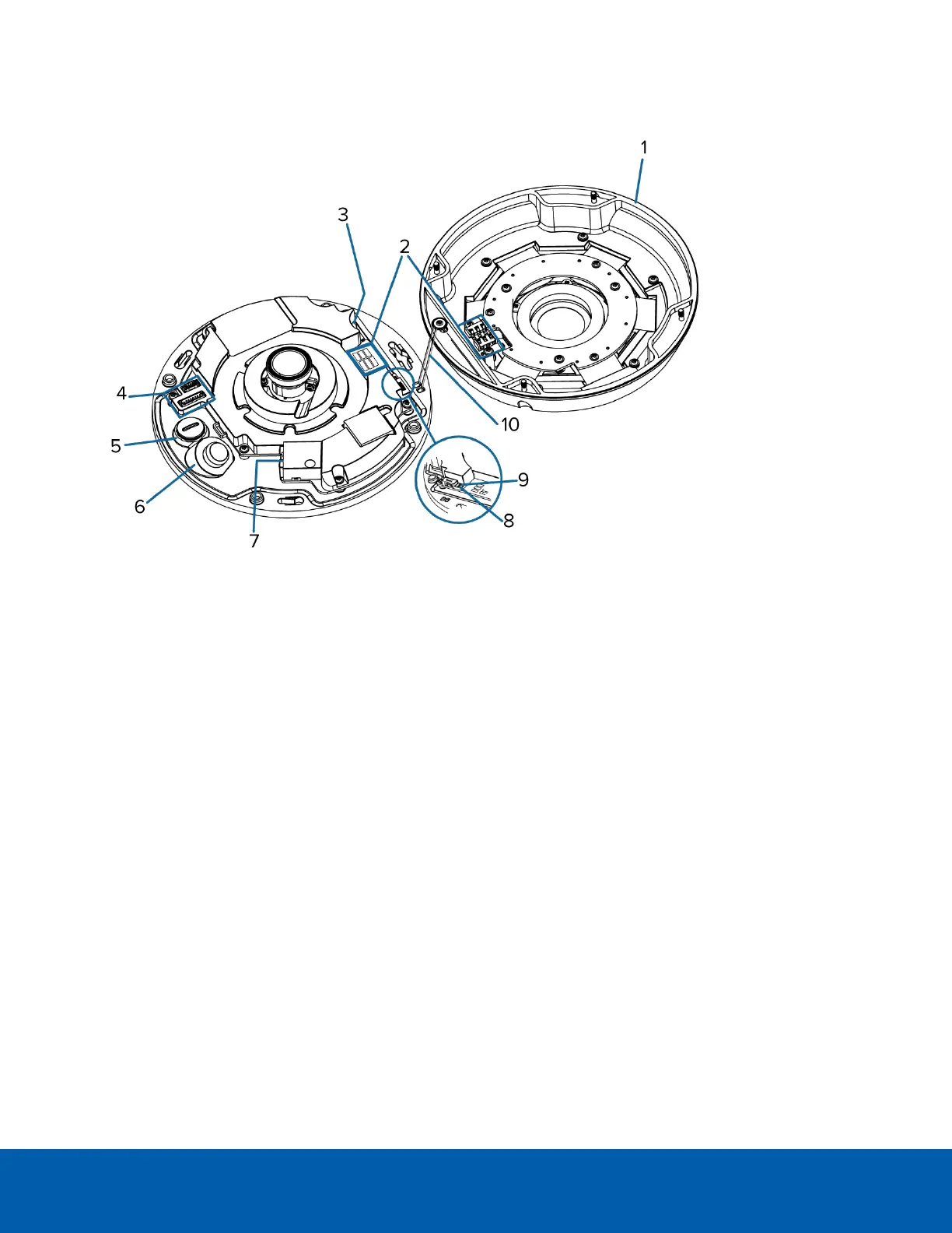
Internal View
1.
Dome cover
Vandal resistant dome cover.
2.
IR contacts
Align the IR contacts when installing the dome cover to the base. The contacts must be connected to
use the IR illuminators.
3.
microSD card slot
Accepts a microSD card for onboard storage. For more information, see (Optional) Configuring
microSD Card Storage on page10.
4.
Auxiliary cable connector
Accepts an auxiliary connection for connecting the camera to auxiliary power, audio and I/O devices.
5.
Auxiliary cable entry hole
An entry hole for the auxiliary cable.
6.
Ethernet cable entry hole
An entry hole for the Ethernet cable.
7.
Ethernet port
Accepts an Ethernet connection to a network. Server communication and image data transmission
occurs over this connection. Also receives power when it is connected to a network that provides
Power over Ethernet.
8.
Link LED indicator
Amber LED indicates if there is an active connection in the Ethernet port.
9.
Connection status LED indicator
Internal View 2