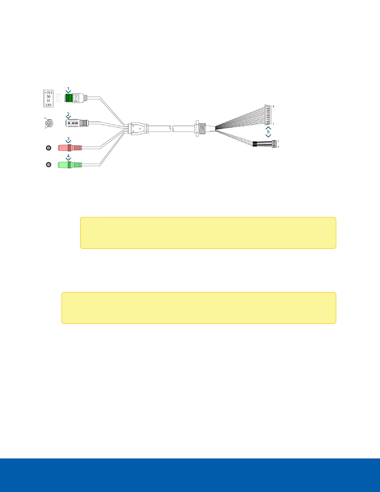
Auxiliary Cable Connections
The auxiliary cable that is provided with the dome camera includes an I/O terminal, external power connector,
audio input and audio output connectors. Connect all the required external devices to the auxiliary cable:
1. Connect external input and output devices to the I/O terminal block. External input and output devices
can include: door contacts, relays, etc.
o
+3V3 — Power, 3.3V DC, 100 mA max
o
DO — Digital output
o
Note: Maximum load is 25 VDC, 50 mA.
o
DI — Digital input
o
GND — Ground
2. If the camera will be using external power, connect a 12 V DC, 2.125 A min. polarized power adapter to
the black power connector.
Note: Do not connect external power if you are powering the dome camera by PoE.
o
Positive on the center pin
o
5.5 mm outer diameter
o
2.1 mm inner diameter
3. Connect an external microphone or a line level input to the pink audio input connector. It accepts a
3.5mm audio connector.
Auxiliary Cable Connections 32