Do you have a question about the AVL DITEST Speed 2000 and is the answer not in the manual?
Presents a summary of critical safety warnings and precautions for device operation.
Explains the use of structure-borne and air-borne signals for speed measurement.
Lists the essential components included in the AVL DITEST Speed 2000 basic package.
Details adapter packages for connecting to AVL exhaust gas testers.
Describes the universal adapter package for other exhaust gas testers.
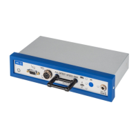
Identifies and explains the purpose of various sockets and indicators on the device.
Illustrates the connection process using AVL DiGas 2200 as an example.
Details connecting the device to other testers using the universal adapter.
Explains connecting via the trigger clamp bar for speed measurement.
Guides through the calibration and measurement steps using status LEDs.
Provides specific considerations for attaching the sensor and performing measurements on motorbikes.
Shows practical examples of how to mount the AVL Dual Sensor on an engine.
Explains the meaning of different LED colors and patterns for status indication.
States that the device requires no special maintenance, but cleaning the sensor is recommended.
Provides instructions on how to properly clean the AVL Dual Sensor.
Describes the device's power-on self-test feature and error indications.
Addresses issues with speed recovery after engine run-out and suggests solutions.
Explains potential speed reading jumps in 4-cylinder diesel engines and how to fix them.
Discusses causes for incorrect speed display and how to perform a reset.
Details engine types, speed ranges, signal inputs, and outputs.
Covers power requirements, operating temperatures, humidity, and protection class.
Lists physical specifications, certifications, and disposal guidelines.
Illustrates mounting points using screw heads and engine brackets.
Shows examples of mounting the sensor on exhaust system components.
Demonstrates mounting using oil drain plugs and brake lever components.
Shows examples of mounting on exhaust clamps and heat guard plates.
Illustrates mounting on the rear axle beam and related components.
Shows examples of mounting near the brake hose mount and cylinder.
Shows how to connect the device with the AVL 4000.
Illustrates the connection using a universal adapter.
Depicts the connection setup using a trigger clamp bar.
Explains the initial status (red LED) and functional control indicators.
Describes the yellow LED indication for captured idle speed.
Explains the green LED indication for captured high speed.
| Category | Measuring Instruments |
|---|---|
| Resolution | 1 rpm |
| Display | LCD |
| Operating Temperature | 0°C to 50°C |
| Storage Temperature | -20°C to 60°C |