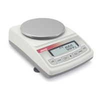
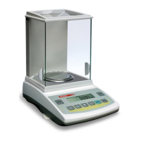
36 USER MANUAL
__________________________________________________________________________________________________________________
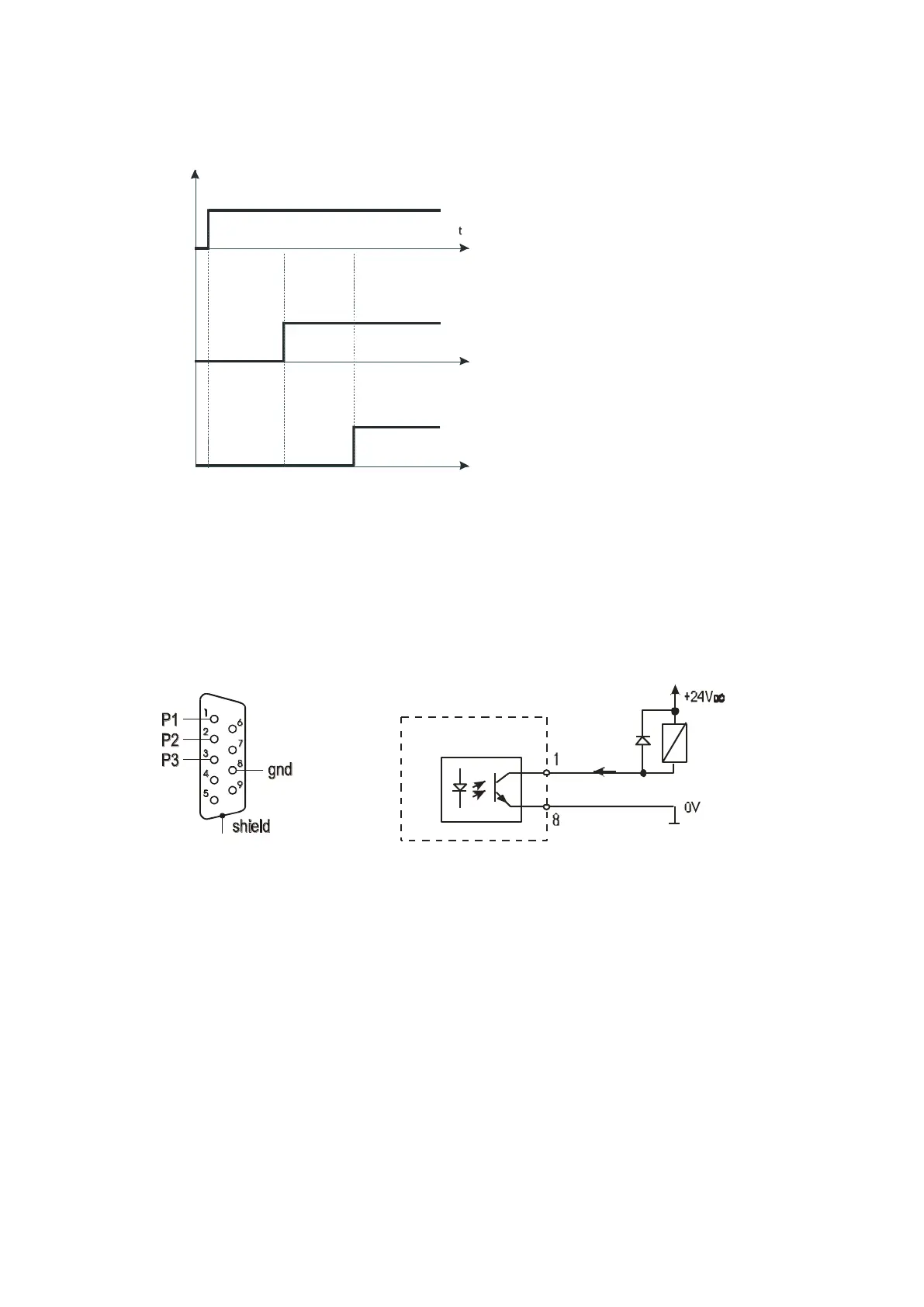
Level mode:
In Batching mode on P1 (thr I) and P2 (thr II) outputs short-circuit impulses
appears for time of 0,5s. On P3 (zero) output short-circuit state appears when
indication does not exceed threshold value signalling zero load.
Relays connection diagram:
Relays output is the open collector transoptor output with load capacity 25mA /
24V. Transmitter inputs must be protected with diodes, e.g. 1N4148.
It is advised to use MS3K/P electronic board (sold separately), consisting of
RM96P transmitters, with DC24V input voltage and AC250V, 3A output.
Important notes:
1. After switching the scale on, both thresholds are set to maximum values.
2. When setting upper threshold value, pay attention that its value is not below
lower threshold value.
3. Setting lower and upper threshold value is possible after sending appropriate
orders from computer, what is described in scale user manual.
.
.
P3
zero
treshold
Outputs:
P1
P2
Min
threshold
Max
threshold
Max
treshold
Min
threshold
ScaleScale Relay
Imax < 25mA