1-2
Chapter 1. OVERVIEW
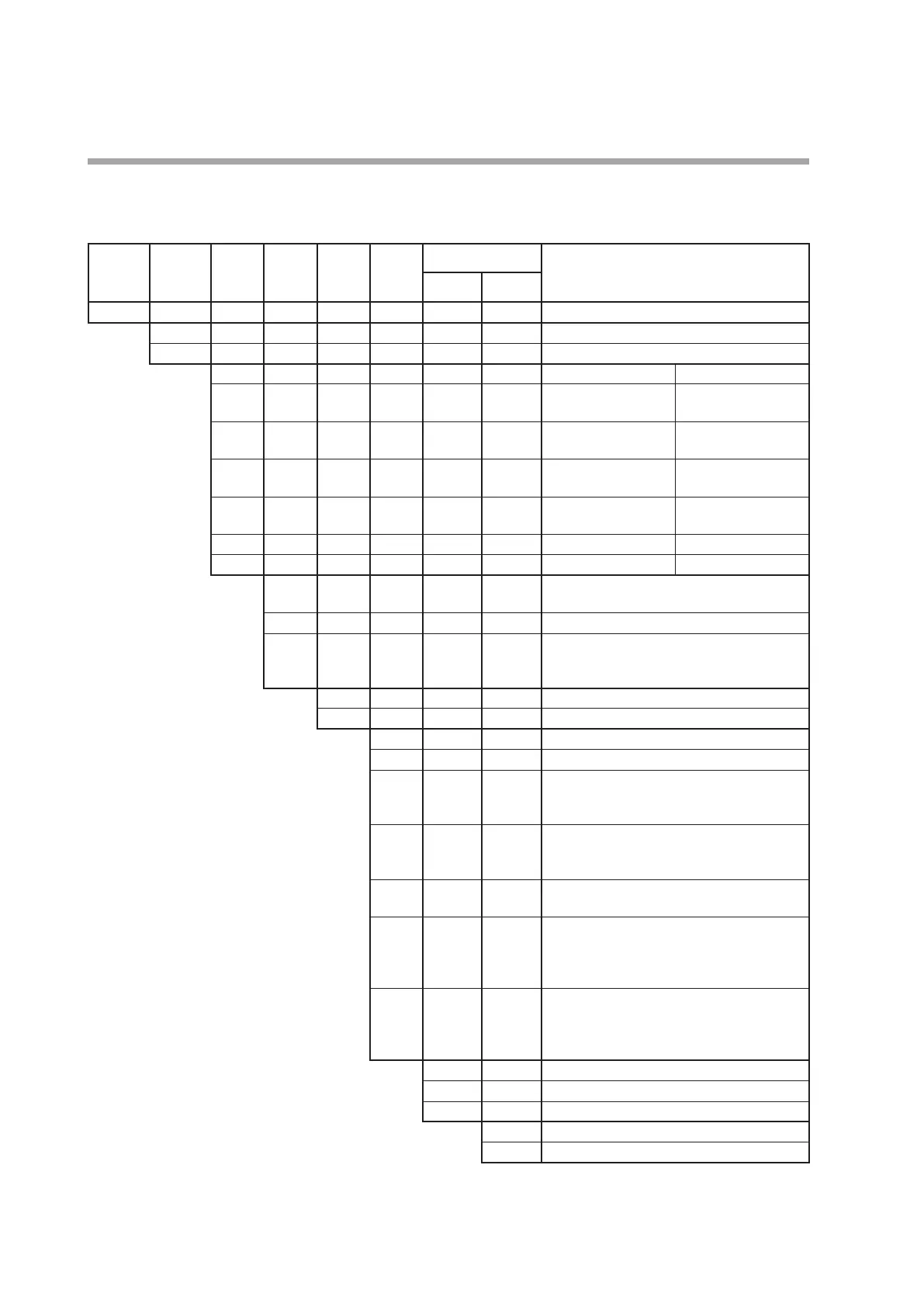
Model selection table
The following shows the model selection table of this unit:
Basic
model No.
Mounting Control
output
PV input Power
supply
Option Additional treatment Specifications
1 2
C15
T Panel mount type
*
1
S Socket mount type
Control output 1 Control output 2
*
2
R0 Relay contact output
NO
None (relay output for
control output 1: NC)
V0 Voltage pulse output
(for SSR drive)
None
*
3
VC Voltage pulse output
(for SSR drive)
Current output
*
3
VV Voltage pulse output
(for SSR drive)
Voltage pulse output
(for SSR drive)
C0 Current output None
*
3
CC Current output Current output
T Thermocouple input (K, J, E, T, R, S, B, N, PL II,
WRe5-26, PR40-20, DIN U, DIN L)
R RTD input (Pt100/JPt100)
L
DC voltage/DC current input (0 to 1 V DC,
1 to 5 V DC, 0 to 5 V DC, 0 to 10 V DC,
0 to 20 mA DC, 4 to 20 mA DC)
A AC Model (100 to 240 V AC)
D DC Model (24 V AC/24 to 48 V DC)
00 None
01 Event relay output: 3 points
*
3
*
4
02 Event relay output: 3 points
Current transformer input: 2 points
Digital input: 2 points
*
3
*
4
03 Event relay output: 3 points
Current transformer input: 2 points
RS-485 communication
*
5
04 Event relay output: 2 points
(independent contact)
*
3
*
4
*
5
05 Event relay output: 2 points
(independent contact)
Current transformer input: 2 points
Digital input: 2 points
*
3
*
4
*
5
06 Event relay output: 2 points
(independent contact)
Current transformer input: 2 points
RS-485 communication
0 No additional processing
D Inspection Certificate provided
*1 Socket sold separately Y Complying with the traceability certification
*2 Only 1a contact is applicable for C15S 0 None
*3 Can not be selected for the C15S. A UL-marked product
*4 Current transformer sold separately
*5 Can not be selected for the DC Model.