4-3
Chapter 4. WIRING
• The part between the control output 1 and control output 2 is not isolated. When
necessary, use an appropriate isolator.
• Make sure that devices and equipment connected to this device have reinforced
insulation suitable for the maximum operating voltage of this device's power
supply and input/output ports.
• This unit is so designed that it does not start functioning for up to 6 s after the
power has been turned ON in order to ensure stable operation. After that, the
unit then enters the operation mode. However, to satisfy the specified accuracy, it
is necessary to warm up the unit for at least 30 min.
IMPORTANT
Terminating resistor
• Do not connect any terminating resistor to both ends of the RS-485
communication path. Doing so might cause the communication to fail.
z
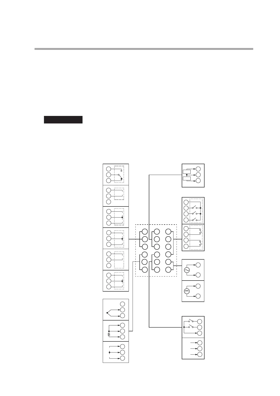
Wiring of C15T
1
2
3
13
14
15
1
2
1
2
3
1
2
3
1
3
1
2
4
5
6
13
14
15
16
17
18
7
8
9
10
11
12
1
2
3
4
5
6
4
5
6
4
5
6
7
8
9
10
7
8
9
10
16
17
18
16
17
18
1
2
+
+
−
−
+
−
+
1
2
+
−
+
−
+
1
2
+
−
+
+
+
−
mA
V
CT1
CT2
11
12
DA
DB
SG
1
2
1
2
1
2
3
C
B
A
11
12
2
Control outputs Current transformer inputs
Event outputs
Relay
Voltage pulse
Voltage pulse
Current
Current
Current
Current
Voltage
Voltage pulse
Voltage pulse
Thermocouple
RTD
Current
Relay
Relay
(independent
contact)
AC power supply
100 to 240 V AC
Digital
inputs
RS-485
Communication
DC power supply
(nonpolar)
Power supply
DI/COM
PV inputs