4-4
Chapter 4. WIRING
z
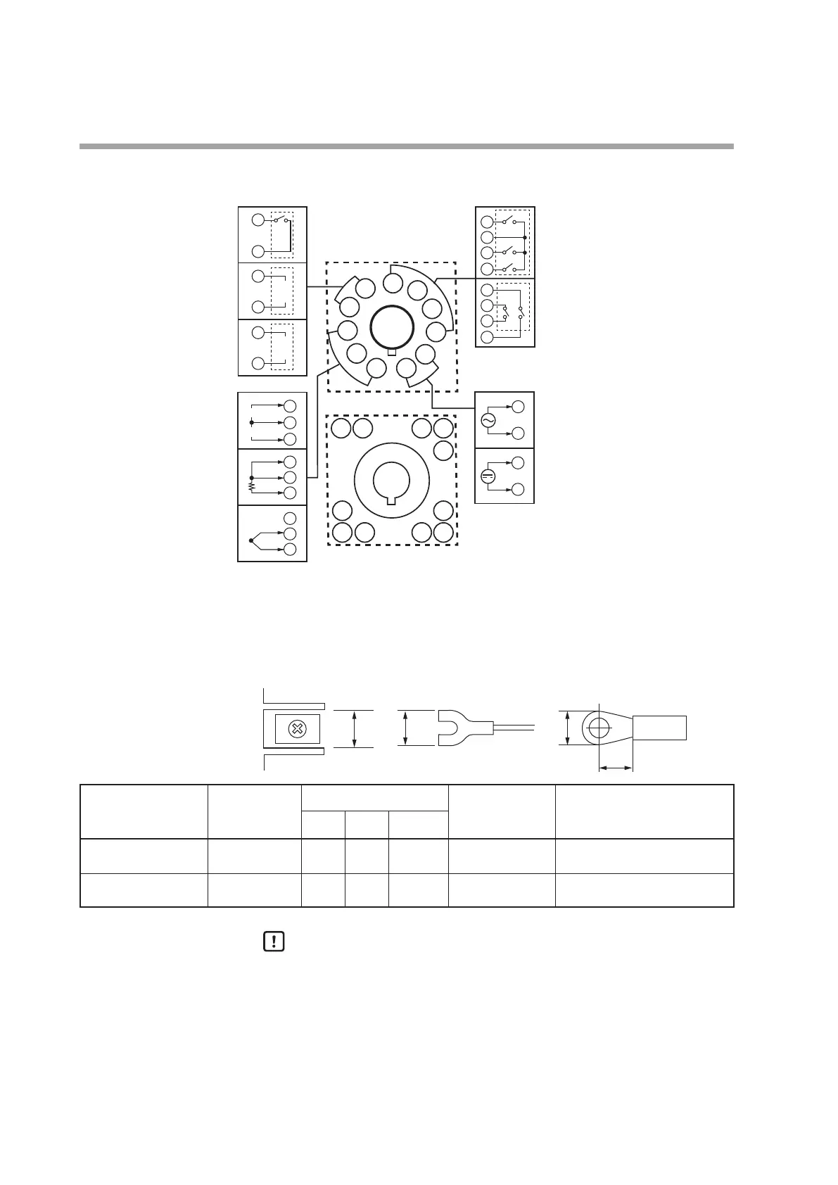
Wiring of C15S
1
11
2
3
4
5
6
7
8
9
10
10
11
6
7
8
9
6
7
8
9
21
3
1
2
3
2
1
3
2
1
3
2
1
+
−
+
+
mA
V
C
B
A
5
4
5
4
5
4
−
+
−
+
5
4
6
2
3
1
10
9
11
78
10
11
Power supply
AC power supply
100 to 240 V AC
Relay
Relay
(independent
contact)
PV inputs
Current
Voltage
RTD
Thermocouple
Control outputs
Relay
Voltage pulse
Current
Socket terminal No.
DC power supply
(nonpolar)
z
Recommended crimp type terminal lugs
For C15T, use an appropriate crimp type terminal lug suitable for the M3 screw.
For C15S socket mounting type, use an appropriate crimp type terminal lug suitable
for the M3.5 screw.
A
B or
less
B or
less
C
Mounting method Applicable
screw
Terminal dimensions (mm)
Applicable electric
wire size
J.S.T. Mfg. Co., Ltd
Model No. (Reference)
A B C
C15T
panel mounting type
M3 6.1 5.8 5.5 to 7.6 0.3 to 1.2 mm
2
AWG22 to 16
V1.25 - MS3 (round terminal lug)
V1.25 B3A (Y terminal lug)
C15S
socket mounting type
M3.5 7.4 6.6 6.3 0.3 to 1.2 mm
2
AWG22 to 16
V1.25 - M3 (round terminal lug)
V1.25 YS3A (Y terminal lug)
Handling Precautions
• When installing this unit in a place where the vibration or impact is
large, always use an appropriate round crimp terminal so that it is not
disengaged from the connection terminal.
• Pay special attention so that no crimp terminals are in contact with
adjacent terminals.