INTRODUCTION
I-E96-207A B - 1
APPENDIX B - TERMINATION MODULE CONFIGURATION
(NICS01)
INTRODUCTION
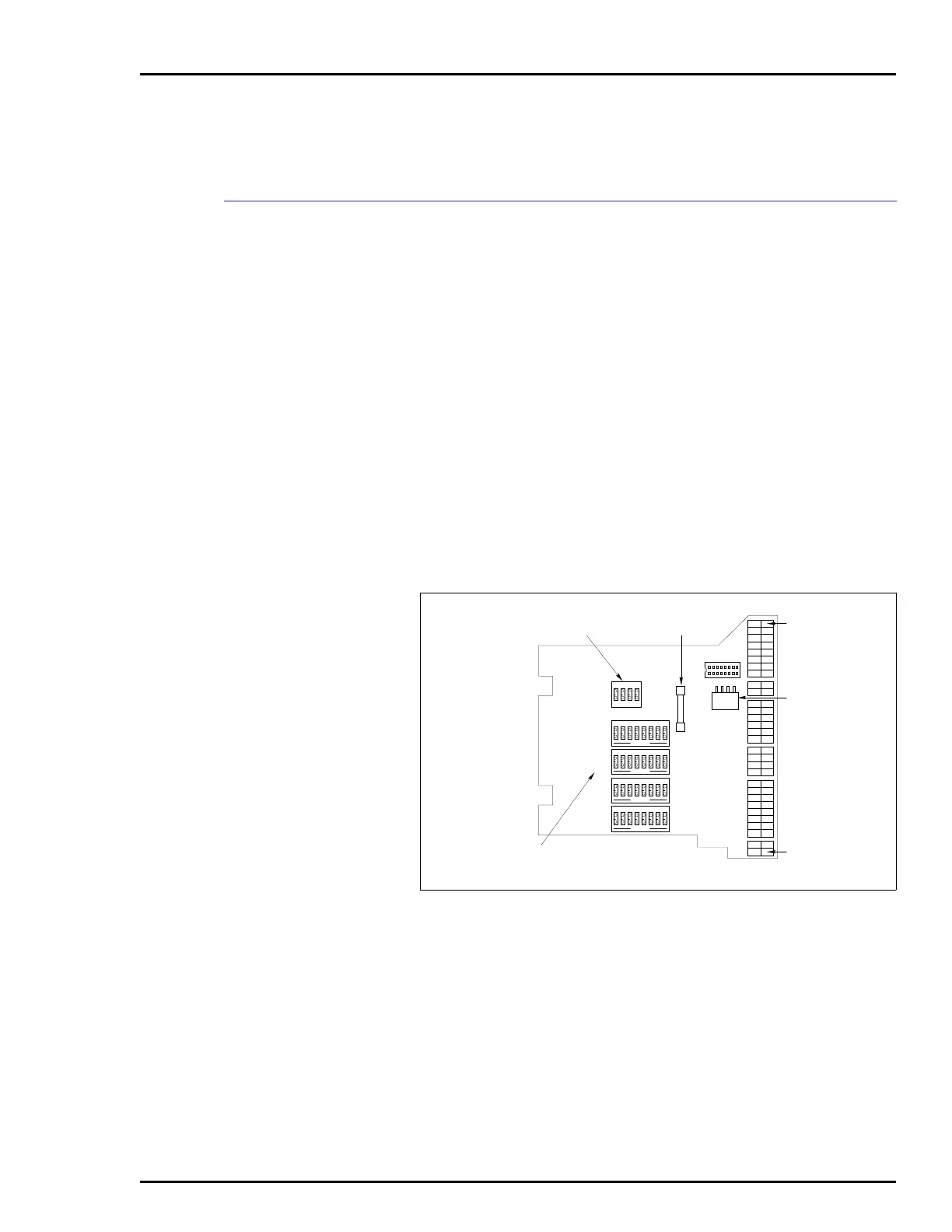
The IMCOM03/04 uses a Termination Module (NICS01) for ter-
mination. The termination module handles 4 analog inputs, 2
analog outputs, 3 digital inputs and 4 digital outputs.
Dipswitches on the termination module configure the I/O. Fig-
ure B-1 shows the termination module.
Refer to Table B-1 to determine the dipswitch settings to con-
figure your application. Figure B-2 shows the terminal assign-
ments for the digital and analog I/O signals. See Figure B-2
when connecting field wiring to the termination module. Figure
B-3 shows the cabling from the termination module to the con-
troller module.
Refer to Appendix A for examples of input/output circuits for
digital and analog signals.
NOTE:
There are no dipswitches to configure for the digital I/O on
the termination module.
Figure B-1. NICS01 Termination Module
P1 EDGE
CONNECTOR
FOR NKTM01 OR
NKTU02 CABLE
ANALOG INPUT
SELECTION SWITCHES
ANALOG OUTPUT
SELECTION SWITCH
4-AMP
FUSE
P1
J1
J2
TERMINAL 30
J2 CONNECTOR
FOR NKTD02
TERMINAL 1
T00134A
1234
OPEN
5678
S1
1234
OPEN
S5
1234
OPEN
5678
S2
1234
OPEN
5678
S3
1234
OPEN
5678
S4
8
9
1
16