INTRODUCTION
I-E96-207A C - 1
APPENDIX C - TERMINATION MODULE CONFIGURATION
(NIDS01)
INTRODUCTION
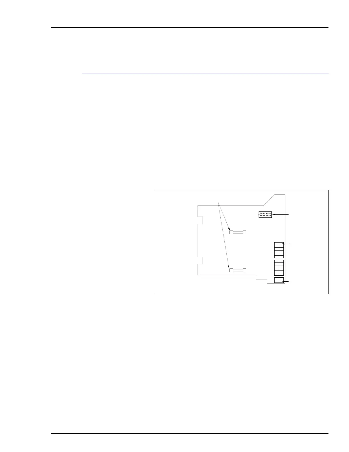
The IMCOM03/04 uses a Termination Module (NIDS01) for ter-
mination. The termination module connects the NICS01 termi-
nation module to a Digital Control Station (NDCS03), Digital
Indicator Station (NDIS01), or Analog Control Station
(IISAC01). Figure C-1 shows the termination module.
Refer to Table C-1 to determine the applications for the IDS.
Table C-2 shows the terminal assignments for the termination
module. Refer to Table C-2 when connecting field wiring to the
termination module. Figure C-2 shows the cabling from the
termination module to the control station or indicator station.
NOTE:
There are no dipswitches to configure on the termination
module.
Figure C-1. NIDS01 Termination Module
P1 EDGE
CONNECTOR FOR
NKTD01 CABLE
4-AMP FUSES
P1
J1
TERMINAL 14
J1 CONNECTOR
TO NICS01
TERMINAL 1
T00137A
8
9
1
16