Section
3–7
MN1229
Control Signal Wiring Continued
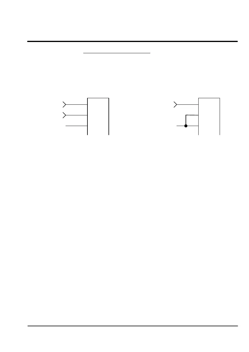
Command Input
The Analog Input at X3 pins 1, 2, and 3 can be wired for single ended or
differential input operation. Figure 3-4 shows these configurations.
Figure 3-4 Command Input Mode
X3
1
2
3AGND
CMD
(–)
CMD (+)
Differential Input
X3
1
2
3AGND
CMD
Single Ended Input
1. Determine if your application requires Single Ended Input (Step 2) or
Differential Input (Step 3) Command Signal wiring.
2. For Single Ended Input wiring:
A. Connect the CMD input wire to X3-1.
B. Connect the command common (analog ground) wire to X3-3.
C. Connect a jumper wire from X1-3 to X1-2.
3. For Differential Input wiring:
D. Connect the CMD (+) input wire to X3-1.
E. Connect the CMD (–) input wire to X3-2.
F. Connect the command common (analog ground) wire to X3-3.
Control Signal Wiring Continued
Command Input
The Analog Input at X3 pins 1, 2, and 3 can be wired for single ended or
differential input operation. Figure 3-4 shows these configurations.
Figure 3-4 Command Input Mode
CMD (+) >
CMD (-) >
AGND
X3
1
2
3
CMD
AGND
X3
Differential Input Single Ended Input
1. Determine if your application requires Single Ended Input (Step 2) or
Differential Input (Step 3) Command Signal wiring.
2. For Single Ended Input wiring:
A. Connect the CMD input wire to X3-1.
B. Connect the command common (analog ground) wire to X3-3.
C. Connect a jumper wire from X1-3 to X1-2.
3. For Differential Input wiring:
D. Connect the CMD (+) input wire to X3-1.
E. Connect the CMD (—) input wire to X3-2.
F. Connect the command common (analog ground) wire to X3-3.
MN1229 3-7
Artisan Technology Group - Quality Instrumentation ... Guaranteed | (888) 88-SOURCE | www.artisantg.com

 Loading...


