Section
3–11
MN1229
Optional Control Signal Wiring
Fault Relay Output (Optional)
A normally closed relay contact is provided at X3-4 and X3-5. This contact can
be used to drive an external fault indicator circuit to indicate a fault condition
has occurred. If a fault occurs the fault must be reset (X3-13). Wire the optional
external fault indicator circuit as follows: (see Figure 3-8).
1. Connect a voltage source to X3-4. (115VAC @ 0.3A or +24VDC @ 0.8A).
2. Connect the relay or circuit load to X3-5.
When a fault occurs, the internal N.C. contact will open and de-energize the
Fault Circuit.
Figure 3-8 Optional External Fault Indicator
X3
4
5
Voltage
Source
Customer
Supplied
Fault Circuit
24VDC External Power Source (Optional)
Caution: To prevent equipment damage, DO NOT connect a 24VDC
source to terminal strip X2 if the 24 Volt option is not
installed. If you apply 24VDC to X2 without the option,
damage to the control will result. Refer to Section 2 of
this manual to identify the model number and determine if
the option is installed.
An external 24 VDC power source can be used as a battery backup feature if
the 24VDC option is installed. This may be identified by the catalog number. If
AC power is lost, the DBSC control circuits are still active.
Connect the external source to connector X2 as follows:
1. Connect the + (Positive) lead to X2-24V.
2. Connect the – (Negative) lead to X2-0V.
Optional Control Signal Wiring
Fault Relay Output (Optional)
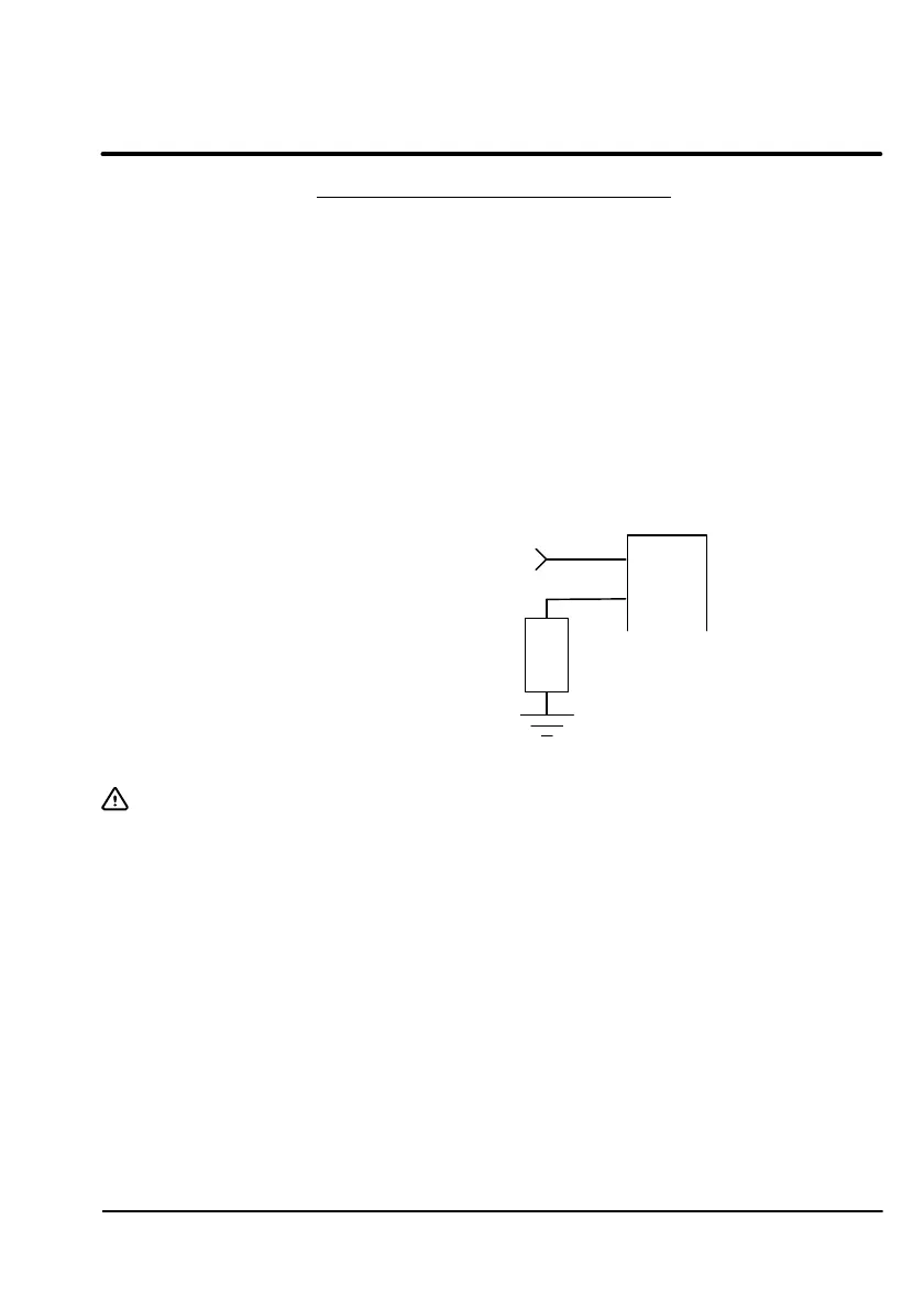
A normally closed relay contact is provided at X3-4 and X3-5. This contact can
be used to drive an external fault indicator circuit to indicate a fault condition
has occurred. If a fault occurs the fault must be reset (X3-13). Wire the optional
external fault indicator circuit as follows: (see Figure 3-8).
1. Connect a voltage source to X3-4. (115VAC @ 0.3A or +24VDC @ 0.8A).
2. Connect the relay or circuit load to X3-5.
When a fault occurs, the internal N.C. contact will open and de-energize the
Fault Circuit.
Figure 3-8 Optional External Fault Indicator
X3
Voltage >
Source
Customer Supplied
Fault Circuit
24VDC External Power Source (Optional)
Caution:
4
5
To prevent equipment damage, DO NOT connect a 24VDC
source to terminal strip X2 if the 24 Volt option is not
installed. If you apply 24VDC to X2 without the option,
damage to the control will result. Refer to Section 2 of
this manual to identify the model number and determine if
the option is installed.
An external 24 VDC power source can be used as a battery backup feature if
the 24VDC option is installed. This may be identified by the catalog number. If
AC power is lost, the DBSC control circuits are still active.
Connect the external source to connector X2 as follows:
1. Connect the + (Positive) lead to X2-24V.
2. Connect the — (Negative) lead to X2-0V.
MN1229
3-11
Artisan Technology Group - Quality Instrumentation ... Guaranteed | (888) 88-SOURCE | www.artisantg.com

 Loading...


