Section
3–9
MN1229
Encoder Output
The encoder output provides position information to the host position controller.
Use twisted pair shielded cable with an insulated overall shield. Connect the
Encoder Output signals to the positioner as follows: (See Figure 3-6).
Figure 3-6 Encoder Output
X7
Channel
B
Channel A
GND
Channel A
Channel C
1
2
3
5
4
6
8
7
9
Channel C
Channel B
1. Connect the Channel A to X7-1 and Channel A to X7-6.
2. Connect the Channel B to X7-2 and Channel B to X7-7.
3. Connect the Channel C to X7-3 and Channel C to X7-8.
4. Connect the GND to X7-5.
The encoder resolution must be set as described in the software manual.
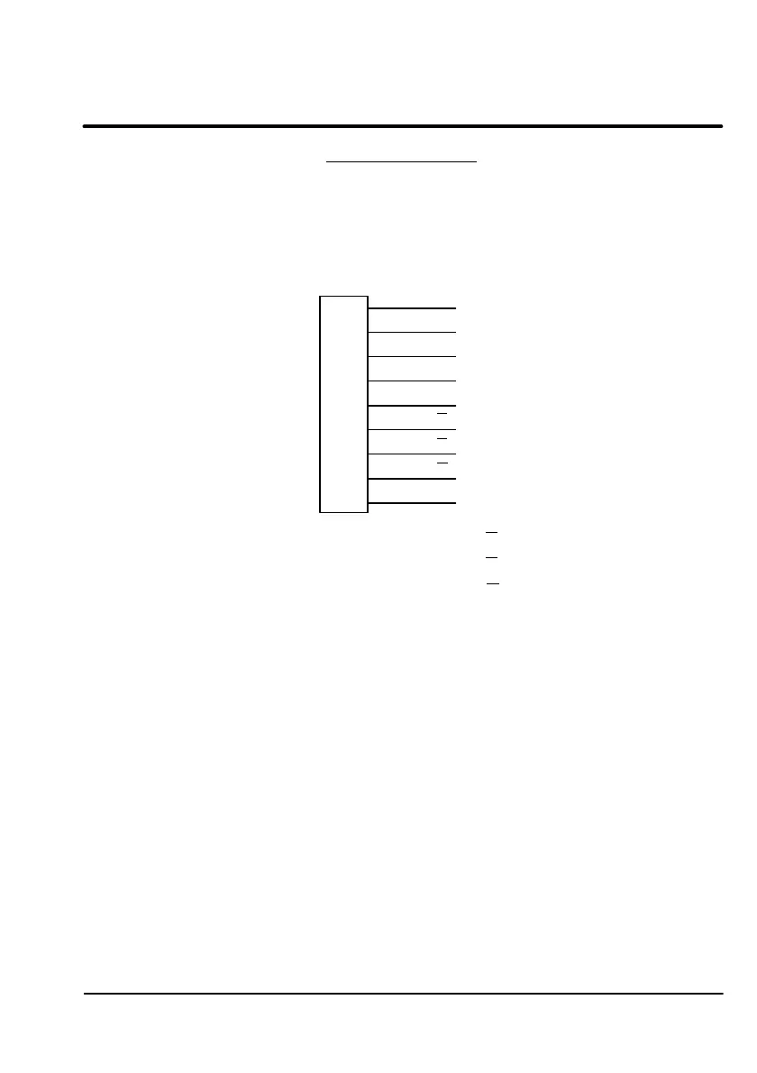
Encoder Output
The encoder output provides position information to the host position controller.
Use twisted pair shielded cable with an insulated overall shield. Connect the
Encoder Output signals to the positioner as follows: (See Figure 3-6).
Figure 3-6 Encoder Output
1
Channel A
Channel B
2
Channel C
3
4
GND
5
Channel A
6
Channel B
7
Channel C
8
9
X7
1. Connect the Channel A to X7-1 and Channel A to X7-6.
2. Connect the Channel B to X7-2 and Channel B to X7-7.
3. Connect the Channel C to X7-3 and Channel C to X7-8.
4. Connect the GND to X7-5.
The encoder resolution must be set as described in the software manual.
MN1229 3-9
Artisan Technology Group - Quality Instrumentation ... Guaranteed | (888) 88-SOURCE | www.artisantg.com

 Loading...


