Section
3–8
MN1229
REGEN Resistor
If the motor is connected to a large inertia load that may require rapid
deceleration, an external REGEN resistor must be installed as follows:
1. Connect one wire from the REGEN Resistor to connector X1-7.
2. Connect the other wire from the REGEN Resistor to connector X1-8.
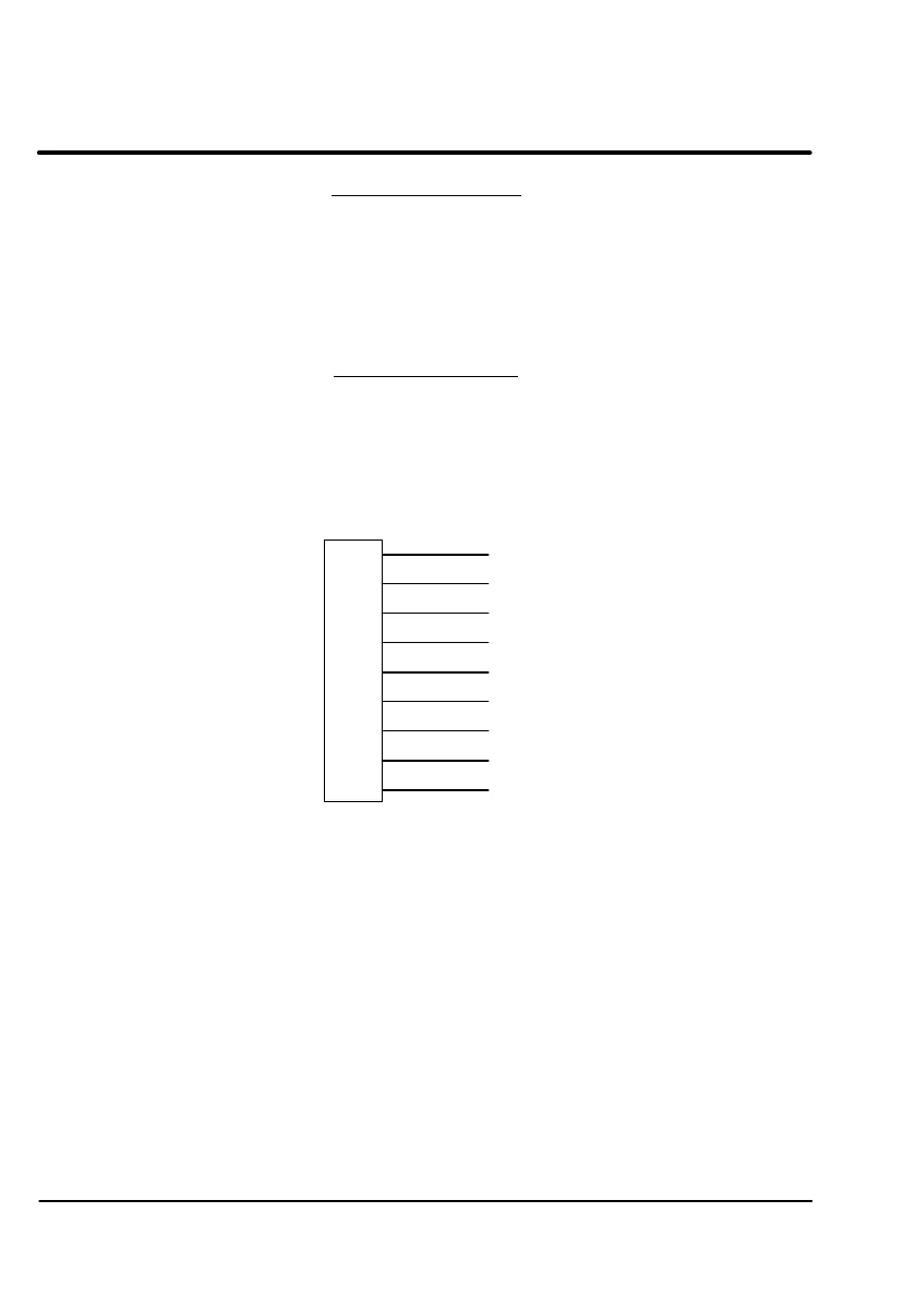
Resolver Wiring
The Resolver interface DB-9 connector is X8 on the DBSC control. Figure 3-5
shows the connector pin numbers and signal names. Use twisted pair shielded
cable with an insulated overall shield.
Figure 3-5 Resolver Interface
X8
COSINE+
REFERENCE+
GND
REFERENCE
–
SINE –
1
2
3
5
4
6
8
7
9
SINE+
COSINE –
1. Connect the Reference + to X8-1 and Reference – to X8-6.
2. Connect Cosine + to X8-2 and Cosine – to X8-7.
3. Connect Sine + to X8-3 and Sine – to X8-8.
4. Connect the Analog Ground wire to X8-5.
REGEN Resistor
If the motor is connected to a large inertia load that may require rapid
deceleration, an external REGEN resistor must be installed as follows:
1. Connect one wire from the REGEN Resistor to connector X1-7.
2. Connect the other wire from the REGEN Resistor to connector X1-8.
1
REFERENCE+
COSINE+
2
SINE+
3
4
GND
5
REFERENCE-
6
COSINE
7
SINE -
8
9
Resolver Wiring
The Resolver interface DB-9 connector is X8 on the DBSC control. Figure 3-5
shows the connector pin numbers and signal names. Use twisted pair shielded
cable with an insulated overall shield.
Figure 3-5 Resolver Interface
X8
1. Connect the Reference + to X8-1 and Reference — to X8-6.
2. Connect Cosine + to X8-2 and Cosine — to X8-7.
3. Connect Sine + to X8-3 and Sine — to X8-8.
4. Connect the Analog Ground wire to X8-5.
3-8 MN1229
Artisan Technology Group - Quality Instrumentation ... Guaranteed | (888) 88-SOURCE | www.artisantg.com

 Loading...


