7-2 Parameter Descriptions MN762
Number
Name
(Display Level)
Value Range, Description and Preset Value
P-03 Motor Rated Frequency Range: 25 to 500 Hz
Preset: 60 Hz (Display shows )
Rated frequency of the motor (listed on the nameplate). Adjusting the Voltage /
Frequency (V/F)
If motor instability is experienced, increase or decrease the voltage (P-37) at the
speed of instability (P-36).
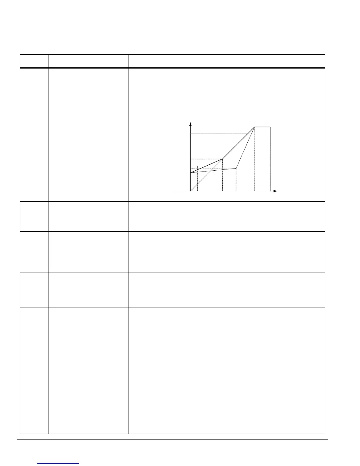
Figure 7-1 Adjusting Volts/Hz Characteristics
P01 [Motor NP Volts]
[P01]/2
P37 [V/F Adj Voltage]
P18 [Voltage Boost]
P05
{Minimum Freq]
[P03]/2
P36
[V/F Adj Freq]
P03
[Motor NP Hertz]
P06
[Maximum Freq]
Frequency
P-04 Motor Rated Speed Range: 0, 360 to 30000 RPM
Preset: 0
The RPM rated speed of the motor (listed on the motor nameplate). When set to
a value other than 0, all speed related parameters are displayed in RPM.
P-05 Minimum Output Speed Range: 0 to P-06 (max 500 Hz)
Preset: 0
Limits the speed reference to the drive regardless of the speed reference
supplied to the drive.
Note: When P-04 is set to a value other than “0”, the value displayed will be
in RPM.
P-06 Maximum Output Speed Range: P-05 to 5 times P-03 (max 500Hz)
Preset: 60.0
User specied maximum motor speed, speeds greater than this are not allowed.
Note: When P-04 is set to a value other than “0”, the value displayed will be
in RPM.
P-07 Start/Stop Source Range: 0 to 6
Preset: 0
0 - Terminal Strip
Speed and other commands are from the terminal strip.
1: Keypad control (forward only)
Uni-directional control from the keypad (up down arrows are used to change
the speed reference). The drive must be enabled (control terminals 1 & 2
connected).
2: Keypad control (forward and reverse)
Bi-directional control from the keypad. START changes between forward
and reverse, and change speed). The drive must be enabled (control
terminals 1 and 2 connected).
3: MODBUS
Network control using internal accel / decel ramps.
4: MODBUS
Network control with accel / decel ramp adjustment via modbus.
5: User PI control with external feedback signal.
6: User PI control with analog input 1 summation.
Sets the input source for Speed, Start/Stop and other commands.
Table 7-1 Parameter Descriptions Continued
 Loading...


