BTL5-A/C/E/G1_-M/U_ _ _ _-K-SR 32/K_ _
Micropulse Linear Transducer - Rod Style
4
english
3 Installation (cont.)
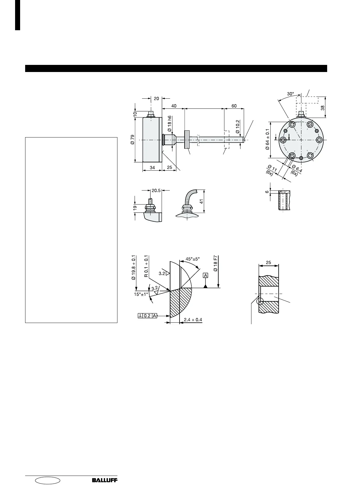
3.2 Transducer, Installation
The smallest permissible distance
between magnet ring and rod
mounting surface is shown in
Fig. 3-2.
The sealing is carried cut with the
O-ring supplied at the flange facing.
Important Installation Notes:
The contact surface of the trans-
ducer must be completely con-
tacted by the mounting surface.
The O-ring supplied must make a
perfect pressure seal, i.e. the
bevel for the O-ring must be con-
figured exactly as shown in
Fig. 3-3.
To achieve a secure mounting,
attach the transducer with all
6 cylinder head screws ISO 4762,
M6 x 16 - A2-70 (
➥➥
➥➥
➥
Fig. 3-2). All
screws must be tightened to
3.5 Nm.
For horizontal mounting of trans-
ducer with stroke lengths greater
than 500 mm, the pressure tube
should be supported or attached
at its end.
When installing in a hydraulic
cylinder, do not allow the magnet
ring to rub against the pressure
tube. The bore diameter in the
piston and cylinder rod should be
at least 13 mm.
BTL5...K-K05
BTL5...K-SR 32
Damping zone
(unusable area)
threaded hole
M4 x 4/6 deep
Nominal
length
= stroke
Mounting surface
Connector BKS-S 33M
rotates in 90° steps
Magnet ring
6 holes for
mounting the
transducer
Fig. 3-2: Transducer BTL5...K..., dimensions
Fig. 3-3: Thru-hole design for mounting BTL with O-ring
thru-hole
Bevel for O-Ring 15.4 x 2.1
 Loading...