11. Lenses and Lens holder
1
2
3
4
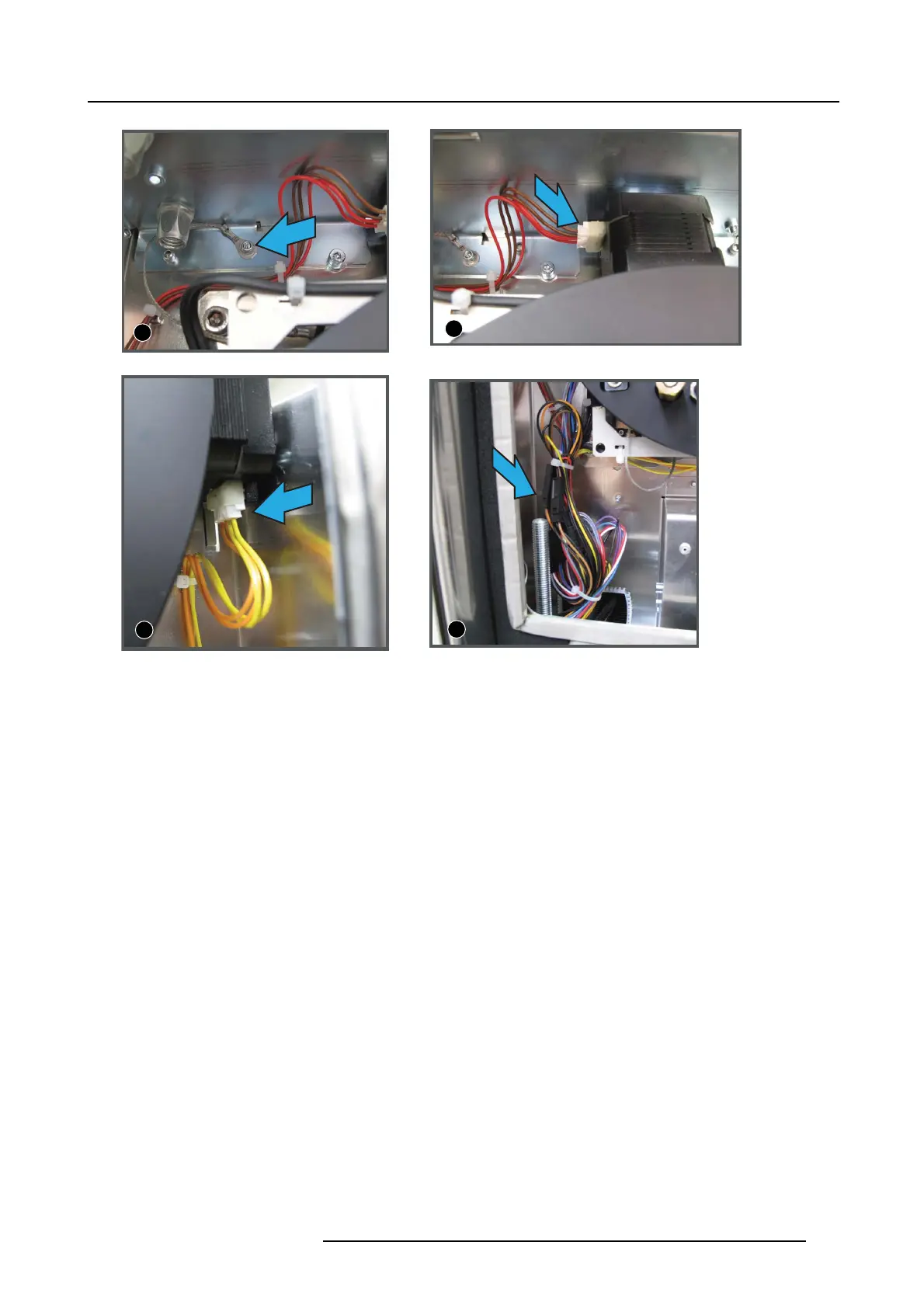
Image 11-12
Electrical connections, image view
2. Unplug the connector of the top m otor (image indication 2) (brown and red wires).
3. Unplug the connector of the side motor (image indication 3) (yellow and oran ge wires).
4. Disconnect all c onnectors of the wire set ( 4x 2 pins connectors and 2x 6 pins c onnectors) (image indication 4).
If necessary, cut the wire ties.
Remove lens holder
1. Remove the 4 hex agon socket heat screws (1 to 4).
R5905043 DP2K-12C/11CX 19/02/2018
187

 Loading...


